


Chapter 2 - Installing the Yamaha CDR400At Drive
5
Chapter 2 - Installing the Yamaha CDR400At Drive
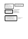
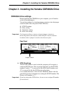
CDR400At drive settings
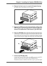
Before installing the CDR400At in your computer, you will need to
set the following jumpers.
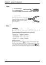
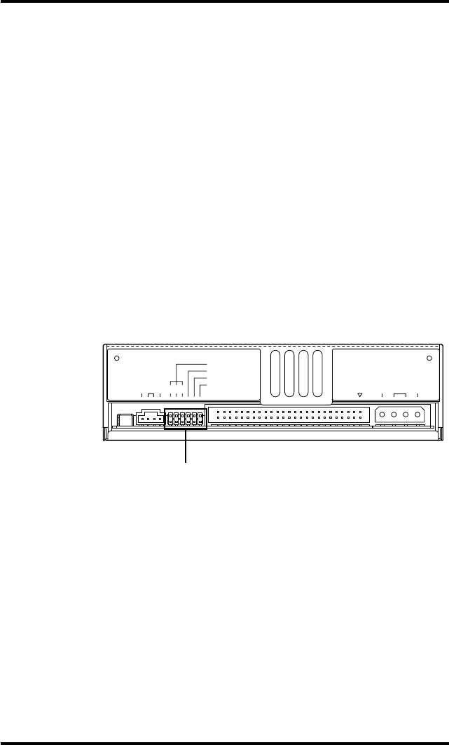
You set these jumpers by inserting jumper connectors into the jumper
switch located on the rear panel of the CDR drive.
♦
SCSI ID settings
♦
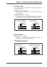
Parity setting
♦
Terminator setting
♦
Block size setting
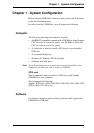
Important:
Use long-nose pliers to remove or insert jumper connectors.
In the diagrams in this manual, solid black fill is used to indicate
locations where a jumper is used to short between pins.
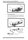
Rear Panel
♦
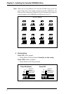
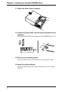
SCSI ID settings
The SCSI ID number is used so that the computer will recognize a
connected SCSI device. You can assign 0 through 7 as the SCSI ID
number. Usually, “7” is reserved for the SCSI card ID number, and
“0” is reserved for the first SCSI device in the chain.
Use a number between 1 and 6 for the CDR400At. Refer to the dia-
gram below for more information on setting the SCSI ID number. The
factory set ID number is “3”.
Important:
If you are using other SCSI devices, be sure to use a unique ID number
for each device.
AUDIO OUT
RGL
ID SELECT
PARITY
TERMINATOR
BLOCK SIZE
1 2 4
1G
SCSI
INTERFACE
CONNECTOR DC INPUT
5V
+
12V
+
Jumper Switch