


E-7
English
AM
ANT
GND
FM
ANT
75Ω
UNBAL.
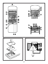
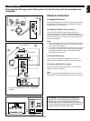
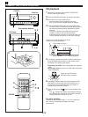
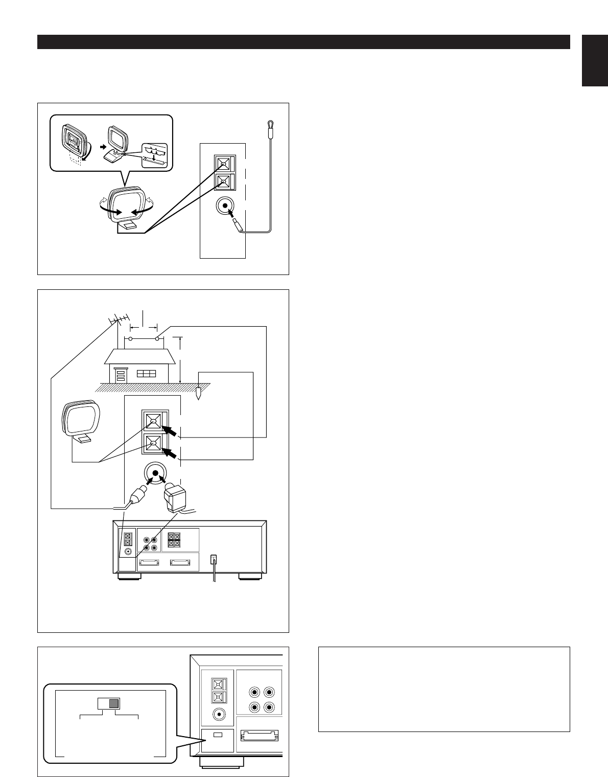
Antenna connection
(1) Supplied FM antenna
Connect the FM antenna wire to the corresponding terminal
and direct the FM antenna wire to the direction where the
strongest signal can be received.
(2) Supplied AM (MW/LW) loop antenna
Connect the AM (MW/LW) loop antenna wires to the
corresponding terminals. Position the AM (MW/LW) loop
antenna for optimum reception. Place the AM (MW/LW) loop
antenna on a shelf etc., or install it on the rack or wall with
screws (not supplied).
Notes
•
When static is still heard even after adjusting the position
of the AM (MW/LW) loop antenna, try reversing the wire
connections (top to bottom).
•
Do not place the AM (MW/LW) loop antenna on the unit. It
will result in noise generation, since the unit is equipped
with digital electronics. Place the AM (MW/LW) loop
antenna away from the unit.
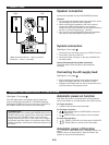
(3) External FM antenna
Use an external FM antenna instead of an indoor FM
antenna if you need better reception. Consult your dealer.
(4) External AM (MW/LW) antenna
Use an external AM (MW/LW) antenna if you need better
reception. Consult your dealer.
Note
When using an external AM (MW/LW) antenna, be sure to
keep the wire of the AM (MW/LW) loop antenna connected.
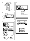
CONNECTIONS
AM
ANT
GND
FM
ANT
75Ω
UNBAL.
or
Earth rod
7.5 m (25 feet)
15 m (49 feet)
* For U.K. and Europe models, “AM” is replaced by
“MW LW”.
(1)
(2)
(3)
(4)
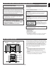
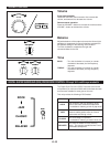
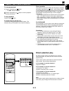
FREQUENCY STEP switch (General model only)
Because the interstation frequency spacing differs in
different areas, set the FREQUENCY STEP switch
(located at the rear) according to the frequency spacing in
your area. Before setting this switch, disconnect the AC
supply lead of this unit from the AC outlet.
Never plug the AC supply lead of this system into the AC outlet until all connections are
completed.
100 kHz
10 kHz
FM
AM
50 kHz
9 kHz
FREQUENCY STEP