


Installation Manual
XMD076A
XMD076A-3 Information is subject to the 5
Rev C, 06/22/06 restrictions on the title page
H E A D S U P T E C H N O L O G I E S
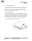
2.3 XMD076A Receiver Installation
2.3.1 Installation Considerations
The XMD076A is intended for application as a “sensor” to the MFD, providing a datalink
to the weather information transmitted by XM Satellite Radio. The software contained in
the XMD076A meets the requirements of RTCA DO-178B, Level E.
2.3.1.1 Location
The XMD076A shall be installed in any interior location of the aircraft that is within the
environmental limits specified in Section 1.2.1. The receiver location should be at least
12 inches away from transmitting radio equipment and is within 40 feet of cable to the
XM antenna.
2.3.1.2 Orientation
The XMD076A can be positioned in any orientation, however the effects of condensation
that could develop in the selected area of the aircraft should be considered. If the
XMD076A is located in such areas, the XMD076A should be positioned to prevent
condensation from entering the D-Sub inter-connect as water wicks through the wire
harness. Drip loops routed in the harness can usually prevent such action.
Another consideration to the orientation of the XMD076A is to allow easier viewing of the
on-board power-on indicator during troubleshooting. The power LED is located next to
the main interface connector, J1.
2.3.1.3 Cooling
The XMD076A is not equipped with air vents or fans, which can be blocked and
therefore this consideration is not required.
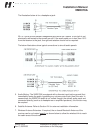
2.3.1.4 XMD076A and XMC050 Communications
The wireless communications between the receiver and the controller uses Bluetooth
Class 2 technology. This wireless link has a line-of-sight (LOS) range of at least 25-ft.
Since the XMD076A is typically located in remote locations of the aircraft, this range
must be considered. In addition, if the XMD076A is located in an effective radio
frequency shielded area, the link may be weak or unable to be established.
In such cases where the location of the XMD076A may produce undesired operation
with the XMC050 controller, the on-board antenna of the XMD076A can be extended.
Refer to Section 2.3.3.1 for more information.
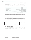
2.3.2 Mounting the XMD076A
The XMD076A should be securely mounted to the aircraft structure using the (4)
provided #10 diameter mounting holes IAW AC 43.13-2A, Chapter 2. An interface