


Installation Manual
XMD076A
XMD076A-3 Information is subject to the 6
Rev C, 06/22/06 restrictions on the title page
H E A D S U P T E C H N O L O G I E S
bracket or plate can be fabricated to attach to the aircraft structure, as required, IAW AC
43.13-2A, Chapter 2.
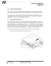
The mounting of the XMD076A enclosure must provide a DC bond to airframe ground of
0.003 Ohms or less.
2.3.3 Electrical Interface Wiring
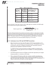
Refer to Appendix C for system wiring diagrams and wire type requirements. Wiring is to
be performed IAW AC 43.13-1B, Chapter 11. The following connectors or similar,
support the XMD076A and antenna installation:
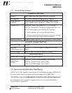
Designation
Box/Wiring
Vendor Part Number Description
P1 Military Specification M24308/2-4F D-Sub 37 Socket (Female)
mates to the XMD076A J1
Ant. IN Tyco/Amp 225532-3 M39012 SMA Plug, Straight
Ant. IN Tyco/Amp 225609-3 M39012 SMA Plug, R/A
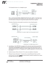
2.3.3.1 Wiring Notes
The following notes apply to aircraft wiring to be used with the XMD076A and antenna
installation:
1. Power, P1-19: Use 22AWG (M22759/16-22 or equivalent) wire fed from a 1-Amp
circuit breaker for both 14V and 28V aircraft.
2. Power Enable, P1-18: Must be energized for system operation. Apply power through
switch or jumper to P1-19.
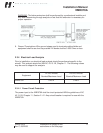
3. RS-232: P1-22, 4 and 23: Use 22AWG shielded triple, M2750022TE3T14 or similar
with a maximum length of 50-feet. Connect dedicated signal ground (J1-23) to the
MFD signal ground. Terminate shield on both ends to the P1 backshell and the MFD
connector shell or chassis ground.
4. Stereo Audio Output: P1-20, 1, 21 and 2. Stereo entertainment audio is provided
from left and right 600-ohm transformer balanced outputs. This stereo entertainment
output has sufficient output impedance and level range to be connected directly to
headphones or to the “music” input of various crew audio panels or intercom
systems. Connection directly to speakers is not recommended.