


®
9
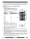
Amplifiers & Preamplifiers
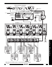
6. As a rule of thumb, use 18 gauge speaker wire for speaker runs up to 30' (9m), 16 gauge up to 70' (21m),
and 14 gauge up to 150' (39m). The 4-terminal connectors accept wire sizes up to 12 gauge max.
7. Strip the insulation back about 1/4" (6mm) and twist the strands on each lead to prevent fraying.
CAUTION: After lead ends are inserted and the screws tightened down, be sure there are no free
strands that could cause shorting!
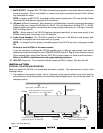
Speaker Phasing
To obtain stable imaging and full bass response, it is imperative that stereo speakers be connected "in
phase" with each other. You can verify this as follows:
a) If the "+" (positive) and "–" (negative) terminals on your speakers are correctly marked, and visible,
and you have wired the system as shown in Figs. 6 and 7, then the system will be "in phase". No further
action is required.
Most manufacturers identify the positive terminal with a red binding post, a "+" sign, or a red dot.
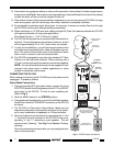
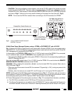
b) If you are unsure of the markings, you can verify the
phasing. Using a mono sound source, such as AM
radio, alternately reverse the leads to one of the
speakers. Pick the connection that delivers a solid
center image between the speakers as well as best
bass response.
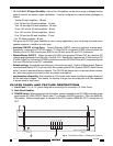
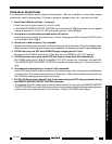
Bridged Mode Connections
In general,
it is recommended that the BRIDGED mode
not be used in multi-room applications where several
speakers are driven through room volume controls and
the like
.
For such applications, use the STEREO mode.
Use the BRIDGED mode for single speaker, higher power
applications, such as in surround sound systems. Use
speakers with an impedance rating of 8-Ohms minimum.
To make connections for the BRIDGED mode, follow the
steps given before for stereo connections, but with the
following differences:
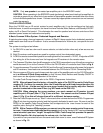
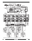
1. You may connect the RCA-type patch cables from the
OUTPUT jacks of the driving preamp or other source
to either the LEFT or the RIGHT input jacks of the
bridged pair, as shown in Fig. 7.
Do this for just the amplifier pairs you wish to run in the
bridged mode.
CAUTION: Be sure Power is OFF when connecting
or switching the amp for BRIDGED operation.
2. Slide the MODE switch to the BRIDGED position.
NOTE: Do this only on the amplifier pairs you wish to
run in the bridged mode!
3. Connect one speaker wire pair between the 4-terminal
"SPEAKER" connectors on the PA1235 and the speak-
ers as shown in Fig. 7. Be sure to use only the two
outer terminals marked "+" and "–" on the 4-terminal
connector as shown on the panel for BRIDGED con-
nections.
COMMON BUS
LOCALLEFT RIGHT
STEREO
MONO
BRIDGED
CI
GROUND
STATUS
IR IN
LEFT RIGHT
SPEAKER
+-- --+
+
BRIDGED
--
1
COMMON BUS
LOCALLEFT RIGHT
STEREO
MONO
BRIDGED
CI
GROUND
STATUS
IR IN
LEFT RIGHT
SPEAKER
+-- --+
+
BRIDGED
--
2
WARNING
TURN POWER
OFF BEFORE
CHANGING
MODES
MODE
MODE
VIDEO
AUDIO
L
R
1
RCA Type
Patch Cords
Preamp Outputs
ZPR68, etc.
PA1235
Rear Panel
Be sure speakers are
connected with correct
polarity as shown.
Speaker Systems
Set MODE
Switches to
BRIDGED position
– +
Right
Left
+ –
Fig. 7 BRIDGED Mode Connections
PA1235