


®
15
Amplifiers & Preamplifiers
TROUBLE SHOOTING
If you encounter a problem, please review the items below. Be sure, in addition, to check other system
components, such as preamplifiers, CD players, speakers, speaker wiring, etc., that may be at fault.
1. Front Panel LEDs do not light – no sound.
• Check line cord for good contact in a live AC outlet.
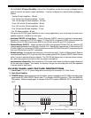
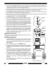
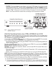
• If the REMOTE MASTER ON/OFF CONTROL terminals (item #12, Fig. 3) are used, be sure applied
voltage is between +5 V and +30 VDC with proper polarity. Refer to Fig. 9.
2. Low level or no sound when operated without IR control.
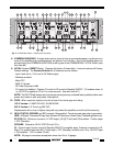
• Level was previously set by IR to a low level or muted. Simply press LEVEL (System) RESET button
as instructed in item 9, Fig.3
3. Sound cuts in and out every 3 to 5 seconds.
• Speaker load impedance is less than 4-Ohms for Stereo mode or less than 8-Ohms for Bridged mode.
Make changes in matching auto-formers and/or speakers as necessary to obtain higher impedance.
4. PA1235 does not turn OFF when REMOTE input voltage goes to 0 Volts.
• Be sure that the POWER switch (item 3, Fig. 2) is set to the MANUAL OFF (Out) position.
5. PA1235 becomes very warm, shuts OFF, but does not come back ON automatically.
• Set POWER switch (item 3, Fig. 2) to MANUAL OFF (OUT) position for 15 seconds, then back ON.
If the REMOTE MASTER ON/OFF CONTROL terminals are used, unplug for 15 seconds, then re-
plug.
6. Unit responds intermittently or not at all to IR commands.
• Look for IR noise at the IR receiver locations in the various rooms. Also, long lengths of shielded wire
from keypads or IR receivers can cause poor IR executions. Refer to the troubleshooting sections of
the IR receiver and keypad manuals you are using.
7. The PA1235 blew its fuse (item #10, Fig. 3) as power was turned OFF using an adapter driving
the REMOTE MASTER ON/OFF CONTROL terminals.
• The supplied 220 Ohm resistor may not have been connected in shunt with the REMOTE MASTER
ON/OFF CONTROL terminals. Be sure the resistor is connected and that the leads are making secure
contact within the screw terminals of the connector. Refer to CAUTION notes, Fig. 9.
PA1235