®
5
Amplifiers & Preamplifiers
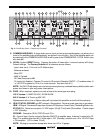
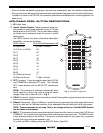
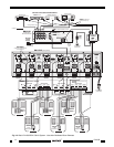
12. SPEAKER Terminals. These plug-in 4-terminal screw type connectors permit speaker wire sizes up
to 12 gauge. When making connections for the STEREO mode, be sure to observe the "+" and "–"
polarity markings, just under the LEFT & RIGHT markings, for each wire pair going to the speakers.
CAUTION: When making connections for the BRIDGED mode, remember, only one speaker is being
attached per amplifier pair. Be sure to observe the outer "+" and "–" polarity markings on each side
of the word "BRIDGED" on the panel above the 4-terminal connector when connecting the 2-conductor
wire to the speaker.
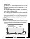
13. REMOTE MASTER ON/OFF CONTROL. This 2-terminal connector allows the entire PA1235 to be
powered ON and OFF by a control voltage ranging between 5 and 30 Volts DC (16mA @ 12 V). Be
sure to observe the marked polarity. For instance, the 12 volt common CO (Control Output) of the
Xantech ZPR68 preamp will power the PA1235 ON and OFF automatically with the first zone ON and
last zone OFF commands.
The DC Voltage must be applied continuously to retain the ON condition and drop to less than 0.5 Volt
to switch to the OFF condition.
NOTE:
The front panel POWER switch (item #3) must be left in the Manual OFF (Out) position
and the Master AC Line Switch (item #17) set to ON (I) to permit the REMOTE MASTER ON/OFF
CONTROL to operate.
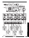
See also CAUTION notes, Fig. 9.
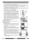
14. Rear Panel ON/OFF LED. This LED indicates the power ON/OFF condition of the entire PA1235,
whether activated by a REMOTE MASTER ON/OFF CONTROL voltage (item #13) or from the front
panel POWER switch (item # 3).
15. Common IR IN and STATUS Connector. This 4-terminal connector provides the same type of IR
control functions as that of the individual amplifier pairs (item #11) except they apply to all amplifier
pairs in common. That is, IR commands for Volume, Mute, etc., control all amplifier pairs together.
NOTE: Individual control of amplifier pairs is possible, however, through the Common IR IN, provided
the IR Code Group is changed on amplifier pairs you wish to control separately.
The STATUS output goes high and low with the AC Power ON/OFF state of the entire PA1235. It does
not respond to a Common IR OFF/ON (Standby) condition.
16. Grounding Screw. Provides a means for chassis connection to earth ground or to other A/V products
to aid in the reduction of system noise, etc., where needed.
17. Master AC LINE ON/OFF Switch. Turns power OFF to the entire PA1235, regardless of IR, Control
IN, or front panel POWER switch conditions. Must be placed in the ON (I) position for the other power
switching functions to work.
18. 3-Conductor AC Line Cord Receptacle. Standard IEC male receptacle for plug-in of a 3-conductor
power line cord. Depending on the application, plug the line cord into a switched or un-switched 120V
60 Hz AC outlet (or 240 VAC 50 Hz on the 240 V version).
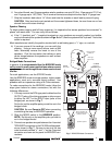
RC68+ (or RC68) PROGRAMMER / REMOTE CONTROL
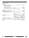
The RC68+ Programmer (available separately) contains all the commands necessary to operate the IR
control functions of the PA1235.
• You will need it to program universal learning devices such as the Xantech URC-2 learning remote, the
Xantech Smart Pads, the 590 Programmable Controller, the 710 Fone Link, etc., with commands that
operate the PA1235.
• NOTE: The RC68+ codes operate many other Xantech models as well, such as the RGC11, CC12,
ZPR68, etc. Therefore, only the button descriptions that apply to the operation of the PA1235 are
listed below. All others should be ignored.
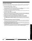
CAUTION: While the RC68+ can be used as a handheld remote control, it is highly recommended it
not be given to the final user for the following reasons:
PA1235


