


®
12
8. To keep the system cost low, no AC power management is included. The user would need to operate
the power switching for each component individually, using front panel power switches, or IR, as
appropriate.
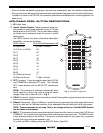
Individual room Standby ON/OFF is provided, however. The STATUS of Standby ON/OFF is indicated
at the IR receivers and keypads via the STATUS line connection to each room, as shown.
9. This system is primarily set up to distribute music to each room. A video feed to a single room could
also be done at low cost. However, video distribution to all rooms would add additional layers of
complexity and cost that would best be handled by a ZPR68-10 in a system similar to that shown in
Fig. 11.
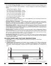
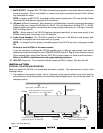
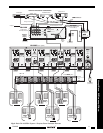
10. When connecting speakers for each room, be sure to observe correct polarities as shown in Fig. 6.
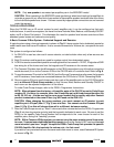
A Basic Dedicated IR System - Non Dedicated Keypads and Remotes.
A typical system of this type is shown in Fig. 10, where each remote room has a Dedicated IR path going
to the PA1235 amplifier pair that controls it. The IR bus is not connected in common as it is in Fig. 8. It
eliminates the need for dedicated remotes,
allowing you to carry the same remote(s) from room-to-
room
- that is, remote commands for Volume, Mute, etc., will work in any room from the same remote.
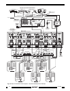
This system is similar in many respects to the previous system (Fig. 8), but differs as follows:
1. A 796-20 Six Zone Connecting Block is used to "zone" individual IR control signals to each amplifier
pair of the PA1235 for Volume, Mute, Balance and Standby ON/OFF action in each room. It also
carries a "COMMON" IR signal to a 789-44 Connecting Block for control of the RS41AV Remote
Switcher and the Source Components.
2. Note that the ZONE numbers on the 796-20 do not agree with the room or amplifier pair numbers. This
is of no consequence; it is only necessary that each room's keypad or IR receiver connects to a different
ZONE IR INPUT on the 796-20.
3. Since the 796-20 channels the IR from each room to it's specific PA1235 amplifier pair, each amplifier
pair can use the same IR Code Group (the factory default A0).
4. While use of the 796-20 entails some added expense, it reduces programming time for both the hand-
held remotes and the keypads, in addition to providing additional convenience to the user.
5. The desired volume and other commands from the RC68+ Programmer (see Fig. 4) need to be
"taught" into learning remote controls (such as the Xantech URC types) and Smart Pads used in the
system, either directly or by using Dragon Drop IR™.
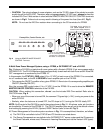
Connecting the REMOTE MASTER ON/OFF CONTROL Terminals
As mentioned under "PA1235 PANEL AND FEATURE DESCRIPTIONS", the REMOTE MASTER ON/OFF
CONTROL terminals allow the power to the entire PA1235 to be turned ON and OFF by a remotely applied
DC Voltage. Figs. 9 and 11 are typical applications using this feature.
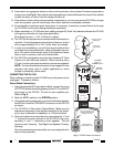
Using a DC Power Adapter as a Control Voltage
Fig. 10 illustrates how a PA1235 can be switched ON and OFF via the switched AC outlet on the rear of
a preamplifier or other control center.
• When the preamplifier Power Switch is switched ON, power is applied to the DC adapter which in turn
applies 5 V to 30 VDC to the PA1235, switching it ON.
• Similarly, when the preamplifier is switched OFF, the DC voltage to the PA1235 is removed, turning it
OFF.
PA1235