


®
8
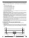
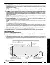
2. If mounted in an equipment cabinet or other confining location, allow at least 2 inches of space above
the top cover (see Fig. 4). Be sure there are large openings in the shelf below the unit and in the cabinet
to allow the entry of cool air and the escape of warm air.
3. If the cabinet contains other heat generating components or you are using several PA1235's in a large
multi-zone system, you will have to pay even closer attention to adequate ventilation.
4. Do not hesitate to use fans (quiet, boxer type), if necessary, to ensure a constant flow of air through
the PA1235's and the other heat generating components.
5. When mounting in a 19" (483mm) rack, adding a single RU (Rack Unit) above and below the PA1235
will improve convection in heavy use applications.
[One Rack Unit size = 1-3/4" (44.5mm) in height].
6. The PA1235 will operate when mounted either horizontally or
vertically. Horizontal placement is preferred, however, since it
will run approximately 5% to 10% cooler when so oriented.
7. In multi-zone installations, you will have large bundles of wire
and cable to accommodate audio, video and speaker connec-
tions. Be sure to allow enough room for the leads and dress
them in such a manner so as not to block airflow.
8. The PA1235 is designed for mounting into standard 19" Rack
Panels or on flat horizontal surfaces. When mounting into a
19" rack, use the rack panel cup washers and screws supplied.
NOTE: You should consider some sort of rear support for rack
mounted units when used in mobile applications or when
located in seismically-active areas.
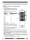
CONNECTING THE PA1235
When making connections to the PA1235 be sure the power cord is
unplugged. Proceed as follows:
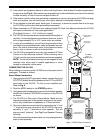
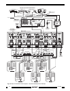
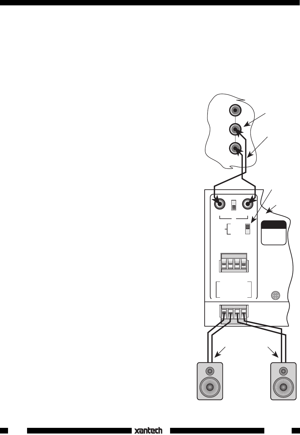
Stereo Mode Connections
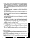
1. Using good quality RCA-type patch cables, connect the L and
R OUTPUT jacks of the driving preamp to the LEFT and RIGHT
input jacks on the PA1235. Do this for each amplifier pair.
Refer to Fig. 6.
2. Slide the MODE switch to the STEREO position.
3. Using good quality speaker wire, connect the individual speaker
leads to the 4-terminal "SPEAKER" connectors on the PA1235
as shown.
4. The PA1235 is 4-Ohm safe in Stereo Mode. Make sure the
impedance presented to the speaker terminals by the speak-
ers (or any combination of speakers) is 4-Ohms minimum.
5. Be sure to observe correct polarity by connecting the "+" and
"–" terminal from each channel on the PA1235 to the corre-
sponding "+" and "–" terminals on each speaker. This will
ensure correct "phasing". See Fig. 6 and Speaker Phasing,
following.
Since the connectors are removable, you may unplug them for
ease of lead assembly.
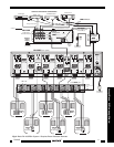
COMMON BUS
LOCALLEFT RIGHT
STEREO
MONO
BRIDGED
CI
GROUND
STATUS
IR IN
LEFT RIGHT
SPEAKER
+-- --+
+
BRIDGED
--
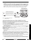
1
WARNING
TURN POWER
OFF BEFORE
CHANGING
MODES
MODE
VIDEO
AUDIO
L
R
1
RCA Type
Patch Cords
Preamp Outputs
ZPR68, etc.
PA1235
Rear Panel
– +
Be sure speakers are
connected with correct
polarity as shown.
Wall speakers,
shelf speakers, etc.
Left Right
Set MODE
Switch to
STEREO position
– +
Fig. 6 STEREO Mode Connections
PA1235