


31
12. Operating Notes
12.1. Operating Level
With any audio signal processing equipment it is necessary to ensure adequate
signal level is used through the device, to avoid sacrificing noise performance. The
TDX2 features a menu selectable choice of operating levels to reduce this problem
(see section 8.6) It is suggested that the operating level chosen should give
adequate level to just light the -6dB LED on the headroom meter with maximum
program level being used. Since the meter is deliberately set to 'over-read' by 3dB,
this still provides 9dB of headroom before clipping occurs. With equalisation in use
it may be necessary to further reduce the input level, as gain within the unit may
cause digital clipping, indicated by the top red LED's lighting.
It should be noted that the figure quoted for the maximum input level options is the
clipping point for that option (not a safe operating level). Always ensure that this
clipping point is no lower than that for the following equipment in the signal chain,
and allow extra margin if equalisation sections are boosted.
12.2. Grounding
The Screen (shield) pins on all audio connectors are normally connected directly to
the ground pin of the IEC mains inlet. The chassis is also directly connected to this
pin. Never operate this unit without the mains safety ground connected. Signal
ground (0V) is in turn connected to the chassis ground.
To avoid ground loops, cable shields should be connected to ground at one end
only. The normal convention is that the shield is only connected at the output XLR.
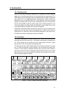
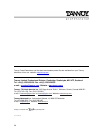
Provision is also made for separately isolating each input and output shield pin
permanently within the TDX2 by breaking the appropriate PCB track, where marked
with a box and an arrow next to each XLR connector using a small drill bit or cutter.
See the following diagram for details.
Figure 7 - XLR pin 1 Isolation points and 10dB pads