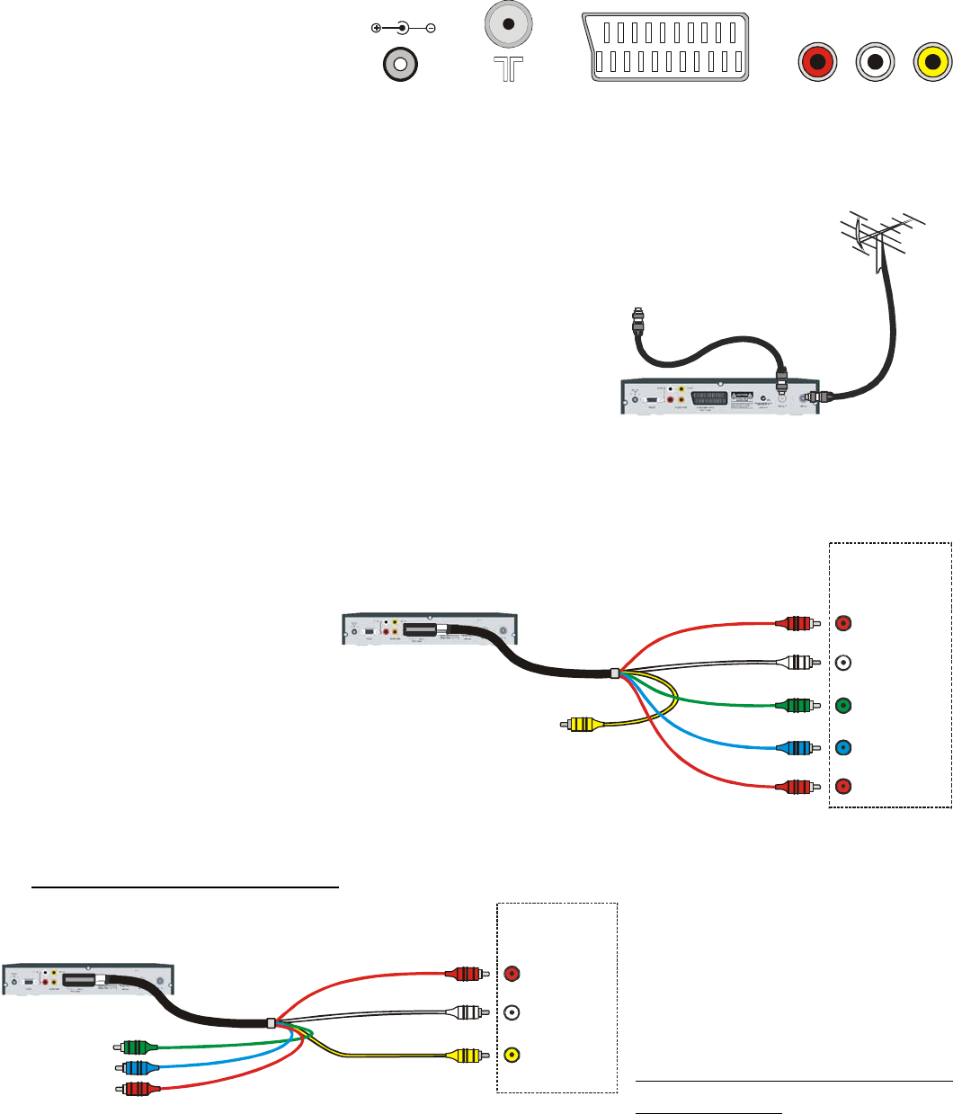
AV I n pu t
R (Red)
AUDIO IN
Y IN (Green)
CVBS OUT (Yellow)
Not used
AUDIO OUT R (Red)
AUDIO OUT L (White)
P OUT
Y
(Green)
POUT
B
(Blue)
P OUT
R
(Red)
P IN (Blue)
B
P IN (Red)
R
L (White)
Television
audio lead to the white audio connector on the television. Remember that you must connect
the video to the same AV Input as the audio.
AV I n pu t
R (Red)
AUDIO IN
VIDEO IN
(Yellow)
Y OUT (Green)
P (Blue)
and P (Red)
Not used
B
R
AUDIO OUT R (Red)
AUDIO OUT L (White)
CVBS OUT (Yellow)
L (White)
Television
VIDEO
If your te
4 Installing Your Digital Receiver - Quick Connect Guide
The Set Top Box and the
television use a number of
different connectors. The main
ones that you need to identify are:
POWER RF SCART RCA
The POWER connector is used to connect mains power (via the power pack) to the Set Top Box.
RF connectors are used for connecting antenna leads. T
connectors are used for video and audio connections.
To TV
he SCART connector and RCA
tart:
nnect the power pack to the Set Top Box. Use the
2 good quality outside /
3 to connect to your television.
t the white
TV has COMPONENT
levision has
so
or
l give the best picture. Connect the
nect the blue
S
1 Co
connector marked POWER.
Connect the Set Top Box to a
roof antenna. Use the connector marked RF IN.
Use the included SCART to RCA connection lead
4 Connect the red audio lead to the red audio connector on the television. Connec
If
VIDEO
If your te
Component inputs (al
called YP
B
P
R
, DVD, YUV
YC
B
C
R
) use them as they wil
red video lead to the red video in connector on the television. Con
to the blue and the green to the green.
Do not connect the yellow lead.
If TV has Composite ( CVBS)
levision does not have
t
r
Component inputs then connect
the yellow lead to the yellow
connector on the television bu
do not connect the green, blue o
red video leads.
Turn the TV and the Set Top Box ON. Using the TV remote control, select the AV Input that the
Set Top Box has been connected too.
7


