


Using The TPA701 MSOP EVM With the Plug-N-Play Evaluation Platform
3-8
Details
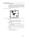
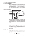
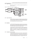
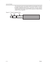
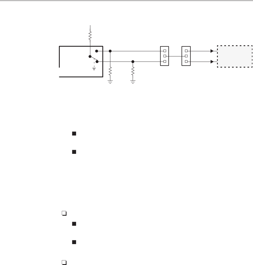
Figure 3–6. Mute/Mode and Polarity Control
J10
Headphone
Jack
R3
240 Ω
R4
1 kΩ
R5
1 kΩ
JP8 JP6
U3, U4
Power
Amplifiers
Lo
Hi
Polarity
Mode
Mute
V
DD
SPK
(U2–U4)
3.3.3.2 Mute/Mode Select (JP6)
A 3-pin jumper header (JP6) on the platform, functioning as a SPDT switch,
routes the control signal from the headphone jack to either the mute control
input pin or the mode control input pin of the evaluation module.
To mute the TPA701 MSOP amplifier module using the control signal
from the platform headphone jack, jumper JP6 to
MUTE.
To not affect the TPA701 amplifier when a plug is inserted into the
headphone jack, jumper JP6 to
Mode
or leave JP6 unjumpered.
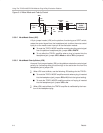
3.3.3.3 Mute/Mode Polarity Select (JP8)
A second 3-pin jumper header (JP8) on the platform selects the control signal
polarity by connecting either the active-high or the active-low line from the
headphone jack to jumper JP6.
When JP6 is set to Mute, use the following JP8 settings for the TPA701:
To mute the TPA701 MSOP amplifier module
when
a plug is inserted
into the headphone jack, jumper JP8 to
Hi
(this is the typical setting).
To mute the TPA701 MSOP amplifier module
until
a plug is inserted
into the headphone jack, jumper JP8 to
Lo
.
When JP6 is set to Mode, the TPA701 amplifier is unaffected by the inser-
tion of the headphone plug.