


Using The TPA701 MSOP EVM With the Plug-N-Play Evaluation Platform
3-7
Details
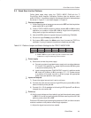
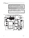
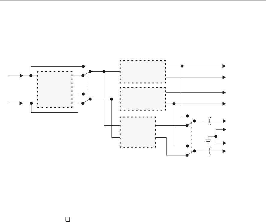
3.3.2 Signal Routing
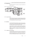
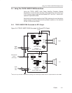
Signal flow on the platform is controlled by two signal routing switches, as
shown in Figure 3–5.
Figure 3–5. Platform Signal Routing and Outputs
U1
Signal
Conditioning
On
Off
U5
Stereo
Headphone
Amplifier
S2
R
L
R
L
L
U5
U2–U4
S3
J10
Headphone
Output
R
L
Audio
Input
R
L
J7, J8, J9
Speaker
Outputs
R
+
+
–
–
U3
TPA701
Amplifier EVM
+
+
–
–
U4
TPA701
Amplifier EVM
GND
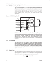
3.3.2.1 Signal Conditioning
The audio signal from the input jacks can be applied to the signal conditioning
socket (U1) if an EVM is installed there, or socket U1 can be bypassed and the
audio input signal applied directly to the inputs of the TPA701 power amplifiers.
Switch S2 selects signal conditioning or bypasses it
3.3.3 Mute/Mode
The TPA701 MSOP EVM is equipped with a shutdown (mute) control input pin.
When this input is tied to V
DD
, the TPA701 amplifier IC on the module shuts
down and assumes an ultra-low power mode. When the EVM control input is
tied to GND or allowed to float, amplifier operation resumes.
In typical applications, as often found in notebook computers, portable audio
products, and such, the internal speakers mute when headphones are
plugged into the headphone jack, or internal speakers mute when external
speakers are connected. In applications using separate speaker and
headphone amplifiers, the one not being used can be shut down (muted) to
conserve power.
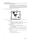
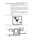
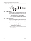
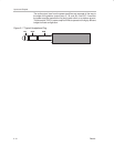
3.3.3.1 Headphone Jack Control Signals
The platform headphone output jack (J10) contains an internal switch that
changes the state of a pair of control lines when a plug is inserted (Figure 3–6).
Each control line is pulled down by a 1-kΩ resistor to ground (R4 and R5). The
switch in the headphone jack pulls one line or the other up to V
DD
through a
240 Ω resistor (R3) depending on whether or not a plug is inserted in J10.