


Quick Start List for Platform
2-3
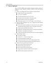
Quick Start
2.2 Quick Start List for Platform
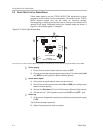
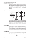
Follow these steps when using the TPA701 MSOP EVM with the TI
Plug-N-Play Audio Amplifier Evaluation Platform (see the platform user’s
guide, SLOU011, for additional details). Numbered callouts for selected steps
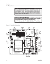
are shown in Figure 2–1 and details appear in Chapter 3.
Platform preparations
1) Ensure that all external power sources are set to
OFF
and that the platform
power switch S1 is set to
OFF.
2) Install a TPA701 MSOP module in platform sockets U3 and U4 for stereo
operation (or a module in either U3
or
U4 for single channel operation),
taking care to align the module pins correctly.
3) Use switch S2 to select or bypass the signal conditioning EVM (U1).
4) Set control signal Polarity jumper JP8 to
Hi.
5) Set jumper JP6 to select the
Mute
control input (causes the TPA701 to
shutdown if a plug is inserted into platform headphone jack J10).
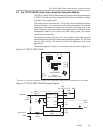
Table 2–2. Platform Jumper and Switch Settings for the TPA701 MSOP EVM
EVM JP6 JP7 JP8 S2 S3
TPA701 Mute X Hi Note 2 X
Notes: 1) X = Don’t care
2) Set S2 to
ON
when signal conditioning board is installed in U1; set S2
to
OFF
when no signal conditioning board is installed.
Power supply
6) Select and connect the power supply:
a) Connect an external regulated power supply set to a voltage between
2.5 V and 5.5 V to platform V
DD
power input connector J6, taking care
to observe marked polarity, or
b) Install a voltage regulator EVM (SLVP097 or equiv.) in platform socket
U6. Install a 9-V battery in B1 or connect a 7 V – 12 V power source
to a platform V
CC
power input J1 or J2 and jumper the appropriate
power input (see platform user’s guide).
Inputs and outputs
7) Ensure that signal source level is set to minimum.
8) Connect the audio source to left and right RCA phono jacks J3 and J5 or
stereo miniature phone jack J4.
9) Connect 8-Ω – 32-Ω speakers to left and right RCA jacks J7 and J9 or to
stripped wire connectors J8.
Power-up
10) Verify correct voltage and input polarity and set the external power supply
to
ON.
If V
CC
and an on-board regulator EVM are used to provide V
DD
, set
platform power switch S1 to
ON.
Platform LED2 should light indicating the presence of V
DD
, and the evaluation
modules installed on the platform should begin operation.
11) Adjust the signal source level as needed.