


Quick Start List for Stand-Alone
2-4
Quick Start
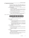
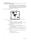
2.3 Quick Start List for Stand-Alone
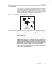
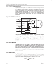
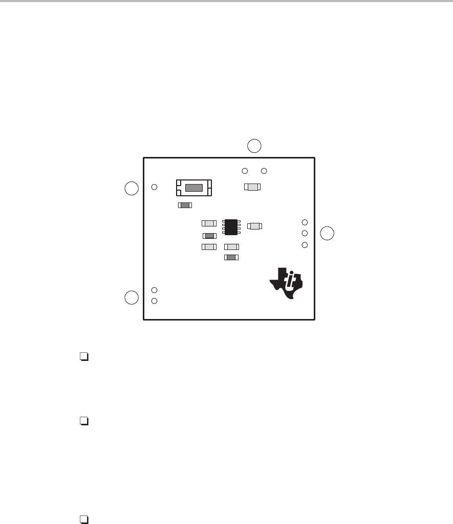
Follow these steps to use the TPA701 MSOP EVM stand-alone or when
connecting it into existing circuits or equipment. Connections to the TPA701
MSOP module header pins can be made via individual sockets,
wire-wrapping, or soldering to the pins, either on the top or the bottom of the
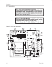
module circuit board. Numbered callouts for selected steps are shown in
Figure 2–2 and details appear in Chapter 3.
Figure 2–2.
Quick Start Module Map
5
2
6
4
OUT+
IN
GND
Vdd GND
U1
†
R2
Shutdown
R3
OUT–
GND
C3
TEXAS
INSTRUMENTS
SLOP213
TPA701 MSOP EVM
C5
C2
C1
C4
S1
R1
+
†
Due to the very small size of the MSOP IC package, the standard part number TPA701 is replaced with the code TIABA
Power supply
1) Ensure that all external power sources are set to
OFF.
2) Connect an external regulated power supply set to 5 V to the module Vdd
and GND pins, taking care to observe marked polarity.
Inputs and outputs
3) Ensure that the signal source level is set to minimum.
4) Connect the audio source to the module IN and GND pins, taking care to
observe marked polarity.
5) Connect the Shutdown (S1) pin to V
DD
through a Normally Open switch.
6) Connect an 8-Ω – 32-Ω speaker to the module OUT+ and OUT– pins.
Power-up
7) Verify correct voltage and input polarity and set the external power supply
to
ON.
The EVM should begin operation.
8) Adjust the signal source level as needed.