Analog Input Conditioning
1-3
Introduction
1.1.1 Stand-Alone Mode
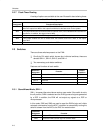
A unique feature of this EVM is the facility it offers the user to closely couple
the ADC and DAC with a minimum of user intervention. This feature allows the
serial bit stream from the digitized analog output to be fed directly to the DAC.
Therefore, the signal that is fed into the ADC can be reconstructed via the
DAC. No DSP need be present.
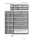
SAM is selected by:
- Switching SW1-1 to the on position, LED is on.
1.1.2 User Mode
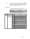
The user can connect the ADC to a DSP or to a microprocessor in two ways:
- Via IDC ribbon cable
- Via daughterboard connectors J16 and J17
User mode is selected by:
- Switching SW1-1 to the off position, LED is off.
For example, TI’s range of DSP starter kits (DSK modules) provides a simple
low-cost solution, offering a range of DSK modules for most needs. The EVM
also supports the TMS320C6000 daughtercard specification (SPRA711), in
addition to providing support for the Motorola specification for data
transfer (SPI).
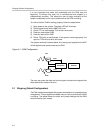
1.2 Analog Input Conditioning
There are a number of methods to connect analog input signals to the EVM.
Chapter 2 discusses these alternatives.
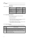
1.3 Analog Output Conditioning
There are a number of methods to connect analog output signals to the EVM.
Chapter 2 discusses these alternatives.
1.4 Prototype Area
An area of the PWB has been set aside if none of the signal conditioning
options provided are suitable.
The prototype area has the following features:
- A matrix of plated-through holes (PTH)
- SMT pads in a standard 14-pin JEDEC footprint
- Convenient points to pick up all power options


