


Host Communication
2-16
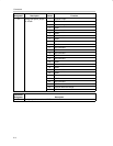
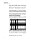
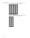
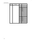
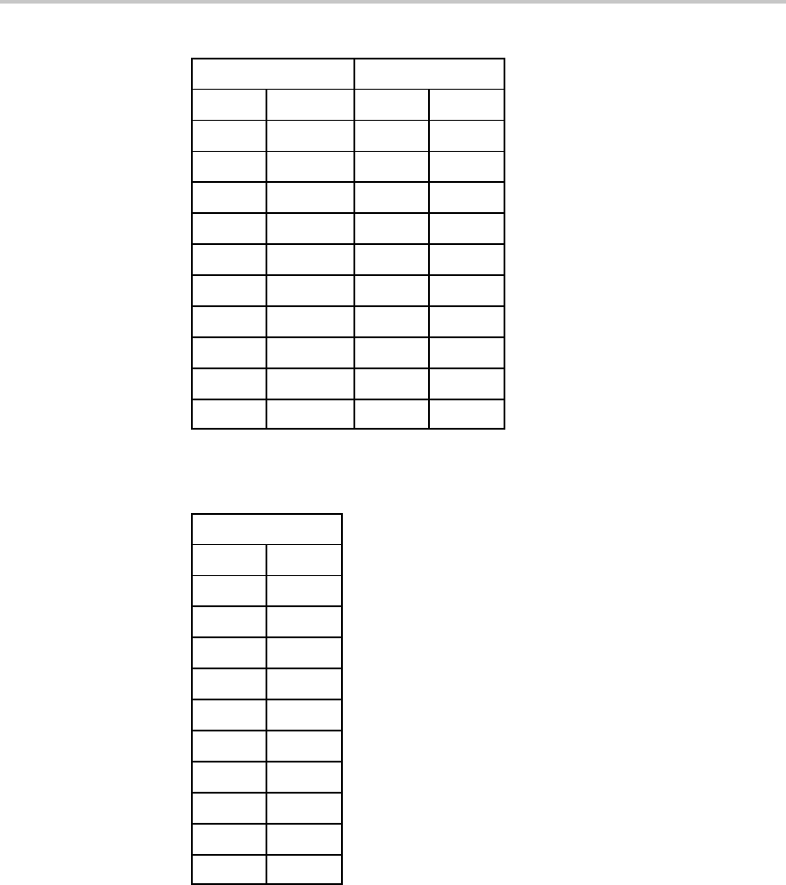
For clarity, the above table can be redrawn with J12 removed.
J13 J15
Pin No. Signal Pin No. Signal
2 NA 1 DGND
4 NA 3 DGND
6 CLKX 5 CLKR
8 TOUT 7 DGND
10 DX 9 DR
12 FSX 11 FSR
14 NA 13 DGND
16 XF 15 DGND
18 NA 17 NA
20 NA 19 CLKS
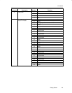
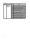
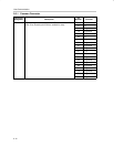
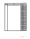
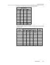
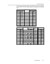
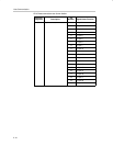
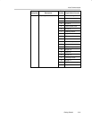
The table below shows the signal names and pin assignments that the
composite connector shown above must be mapped onto.
J13
Pin No. Signal
1 XF
3 CLKX
5 CLKR
7 DX
9 DR
11 FSX
13 FSR
15 Resvd
17 CLKS
19 TOUT