


Jumpers
2-4
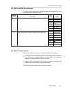
2.2 Jumpers
The table below lists the functions that users can reconfigure along with the
shipping condition.
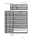
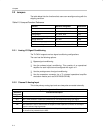
Table 2–3.Jumper/Function Reference
Function Reference Designator Subsection
Channel 0
Analog input W1, W11, W4, W2, W3 3.2.3
Analog output W14, W19, W18 3.2.4
Disable onboard signal generator W9 3.2.7
Voltage reference W16, W17 3.2.8
3.3-V/5-V analog supply select W13 3.2.9
Clock/timer routing W20, W21, W22, W23, W24 3.2.10
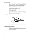
2.2.1 Analog I/O Signal Conditioning
The TLC4541 supports various signal conditioning configurations.
The user has the following options:
- Bypass signal conditioning
- Use the onboard signal conditioning. This consists of an operational
amplifier for each input channel configured with a gain of 1.
- Use the prototype area for signal conditioning.
- Use the expansion connector via a TI universal operational amplifier
evaluation module (such as SLOP224/SLOP249).
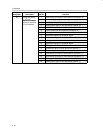
2.2.2 Channel 0 Analog Input
This is the primary analog input and can always be connected externally.
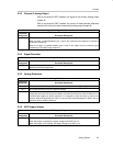
Analog Input Configuration Channel 0
Reference
Designator
Functional Description
W1 W1 allows the user to select between an analog input via BNC – J1 or IDC – J4 pin 1.
W11 W11 allows selection of either the conditioned or nonconditioned analog input signal.
W4 W4 allows the user to select either the prototype area output or the output from W11.
W2 W2 enables the user to select either the output from the expansion connector or the output
from the onboard signal generator.
W3 W3 completes the selection choices for channel 0 by determining if the output from W2 or W4
is chosen to be presented to the ADC.