


Shipping (Default Configuration)
2-3
Getting Started
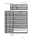
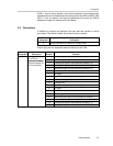
Table 2–1.Default Switch Settings
Switch Settings
Default
Configuration
Description
SW1-1 On Stand-alone mode is selected, LED is on
SW1-2 Off Reserved
SW1-3 Off Reserved
SW1-4 Off Reserved
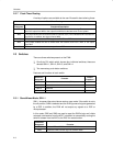
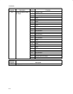
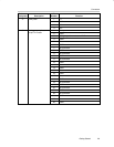
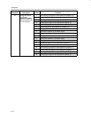
Table 2–2.Default Jumper Settings
Jumper Settings
Default Configuration Description
Pins 1–2 Pins 2–3
W1 Inserted Not inserted Input for channel 0 is via BNC connector J1.
W2 Not inserted Inserted Sine wave test signal is selected for channel 0.
W3 Not inserted Inserted Sine wave test signal is output for channel 0.
W4 Not inserted Inserted Onboard conditioned input for channel 0 is selected.
W5 Not populated Not populated
W6 Not populated Not populated
W7 Not populated Not populated
W8 Not populated Not populated
W9 Not inserted Disables onboard sine and triangle wave generator
W10 Inserted Not inserted SCLK routed to ADC
W11 Not inserted Inserted Signal conditioning output selected for channel 0
W12 Inserted Not inserted FS routed to ADC
W13 Not Inserted 5-V analog
W14 Inserted EVM reference or DAC’s on-chip reference selected.
W15 Not populated Not populated
W16 Inserted Not inserted Selects internal or external reference
W17 Inserted Not inserted Determines EVM reference voltage
W18 Not inserted Inserted FS routed to DAC
W19 Inserted Not inserted Selects source of signal conditioning output from DAC
W20 Not inserted
W21 Inserted Not inserted
These jum
p
ers determine various o
p
tions for su
pp
lying system
W22 Inserted Not inserted
Th
ese
j
umpers
d
e
t
erm
i
ne var
i
ous op
ti
ons
f
or supp
l
y
i
ng sys
t
em
clock. This has been designed to be as flexible as possible to
W23 Inserted Not inserted
clock.
This
has
been
designed
to
be
as
flexible
as
ossible
to
accommodate many potential options.
W24 Not inserted
W25 Not populated Not populated
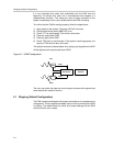
The hardware that can be reconfigured falls into one of the following sections:
- Jumpers
- Switches
- Connectors