


Jumpers
2-5
Getting Started
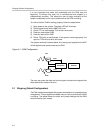
2.2.3 Channel 0 Analog Output
With a one-channel DAC installed, this signal is the primary analog output
(output A).
With a two-channel DAC installed, the pinout of these devices effectively
resolves this channel to be the secondary analog output (output B).
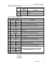
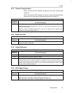
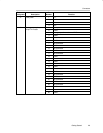
Analog Input Configuration Channel 0
Reference
Designator
Functional Description
W19 This jumper selects the source for the analog output on channel 0.
When a jumper is installed between pins 1 and 2, the output from the expansion connector’s
B-channel is routed out.
When the jumper is installed between pins 2 and 3, the output from the onboard signal
conditioning is directed through channel 0.
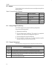
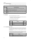
2.2.4 Signal Generator
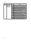
Signal Generator
Reference
Designator
Functional Description
W9 W9 controls the generation of both onboard test signals. A jumper installed between pins 1 and 2
disables the waveform generator.
2.2.5 Voltage Reference
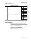
Voltage Reference
Reference
Designator
Functional Description
W16 W16 selects either the onboard reference or an external reference supplied by the user.
W17 W17 allows the user to vary the reference voltage.
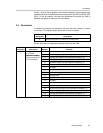
W14 There are a number of possible DACs that a user can install on this EVM. Some have an internal
reference that the user can select via software, and some do not have an internal reference. For
the DACs that support an internal reference, it is important to have the facility to remove the
external reference supplied by the EVM (or user) to avoid conflicts between the DAC’s internal
reference and the external reference.
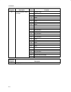
2.2.6 ADC Supply Voltage
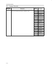
ADC Supply Voltage
Reference
Designator
Functional Description
W13 This jumper controls the analog supply voltage.
When the jumper is installed, the supply voltage to the ADC is 3.3 V.
When the jumper is not installed, the supply voltage to the ADC is 5 V.