


40
Host to US-224 Messages:
Note: In these messages, <STRIP #>is a number in the range [0..3], corresponding to the
channel-strip #, and <STATE>is either 0x00 (LED OFF) or 0x7F (LED ON) . Transmit<UNIT> as
0 for now.
1. UPDATE_MUTE_LED: F0 4E<UNIT>12 02<STRIP #> <STATE> F7
2. UPDATE_SEL_LED: F0 4E<UNIT> 12 03<STRIP #> <STATE> F7
3. UPDATE_REC_LED: F0 4E<UNIT> 12 04<STRIP #> <STATE>F7
4. UPDATE_NULL_LED: F0 4E<UNIT> 12 05 <STATE> F7
5. UPDATE_SOLOMODE_LED: F0 4E<UNIT> 12 06 <STATE> F7
Note: following message forces US-224 to send current fader position messages to host via the
US-224 Control Port
6. DUMP_FADER_POS: F0 4E<UNIT>12 10 <STRIP #> <STATE>F7
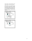
Bank-Switching Command Set
The US-224 has two switches that allow the user to select the bank of application channels that is
addressed by the four channel-strips. For example, an application with 32 virtual tracks would
define eight banks of four channel strips each. The Bank-L and Bank-R switches let the user
quickly shift the control surface to address any bank of four channels. There are two LED's
adjacent to the Bank-L and Bank-R switches, which indicate that pressing the button will cause
the application software to switch to the next lower or higher bank, respectively. It is OFF when
there are no further virtual fader banks available in that direction.
US-224 to Host Commands
• BANK_LEFT:
o Button-down: BF 10 7F
o Button-up: BF 10 00
• BANK_RIGHT:
o Button-down: BF 11 7F
o Button-up: BF 11 00
Host to US-224 Messages:
1. UPDATE_BANK_LEFT_LED: F0 4E<UNIT> 12 07<STATE> F7
2. UPDATE_BANK_RIGHT_LED: F0 4E<UNIT> 12 08<STATE> F7
where<STATE> is either 0x00 (LED OFF) or 0x7F (LED ON) <UNIT>is device ID. Should be
transmitted as 0 for now.
Continuous data wheel
A data wheel is provided for general-purpose parameter modification. In addition to the pan level
setting described above, the data could be used for scrubbing, locating, or any other purpose the
application programmer desires.