10
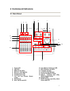
14. Channel Faders
send continuous controller information for
banks of four faders, as selected by the
BANK switch
Master Fader
controls level to the stereo bus output,
and/or sends MIDI controller information to
the host.
15. SELECT Switches
selects channel for editing, recording, etc.
SELECT LEDs
indicates selected status of channel.
RECord Ready Switch
when held, pressing the SELECT button
toggles the selected channel(s)’ record-
ready status.
16. RECord LEDs
indicates record status of selected channel.
17. MUTE Switches
toggles mute or solo status for selected
channel.
MUTE LEDs
when illuminated, indicates mute status of
selected channel. (When SOLO LED is on,
the associated channel’s MUTE LED’s
indicate solo status when lit)
SOLO switch
toggles between mute and solo status.
SOLO LED
when illuminated, indicates MUTE buttons
and LEDs are toggled to solo status.
.
2.4 Rear Panel Descriptions
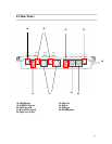
18. PHONES jack
standard 1/4” stereo headphone output.
19. OUTPUT L/R jacks
unbalanced (RCA) analog audio output of
stereo bus.
20. INPUT A and B
Analog inputs A and B. Balanced when
MIC/LINE-GUITAR switch is set to
MIC/LINE; unbalanced when set to GUITAR
21. MIC INPUT A and B
Balanced XLR Inputs A and B.
22. Digital In and Out
S/PDIF digital input and output.
23. MIDI Out
MIDI output
24. MIDI In
MIDI input
25. USB jack
input for USB connection to host computer.
26. POWER switch
push on/push off power switch.


