


User's Manual
51
APPENDIX
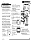
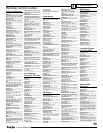
The RS-232 Port
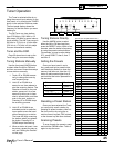
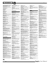
COMMAND ASCII DATA RECEIVED
POWER TOGGLE *111
POWER ON *112
POWER OFF *113
CD *114
TAPE *115
SAT *116
DVD *117
PHONO *118
TUNER *119
VID1 *11A
VCR *11B
VID2 *11C
DSP MODE UP *11D
DSP MODE DOWN *13W
STEREO *11E
PRO LOGIC *11F
PARTY *134
NEO:6 13H
SOURCEDIRECT 13J
JAZZ-CLUB *11K
HOLO TOGGLE *11L
HOLO ON *11M
HOLO OFF *11N
MUTE TOGGLE *11P
MUTE ON *11Q
MUTE OFF *11R
VOLUME UP *11S
VOLUME DOWN *11T
VOL ABSOLUTE *11U + 2 EXT
*11U00 = zero vol
*11U99 = max vol
ZONE2 PWR TOGGLE *13M
ZONE2 PWR ON *13N
ZONE2 PWR OFF *13P
ZONE2 MUTE TGGLE *13Q
ZONE2 MUTE ON *13R
ZONE2 MUTE OFF *13S
ZONE2 VOL UP *13T
ZONE2 VOL DOWN *13U
ZONE2 CD *138
ZONE2 TAPE *139
ZONE2 SAT *13A
ZONE2 DVD *13B
ZONE2 PHONO *13C
ZONE2 TUNER *13D
ZONE2 VID1 *13E
ZONE2 VCR *13F
ZONE2 VID2 *13G
The Receiver has a rear panel
RS-232 Serial communication port.
This allows the Flash memory to be
upgraded to the latest software by
connecting to a PC.
The software may be updated
to reÞ ne operational details and to
include new features. Downloadable
updates will be posted on our website:
www.sunÞ re.com.
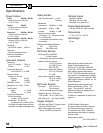
Communications
Serial RS-232, 9600 Baud, 8-N-1
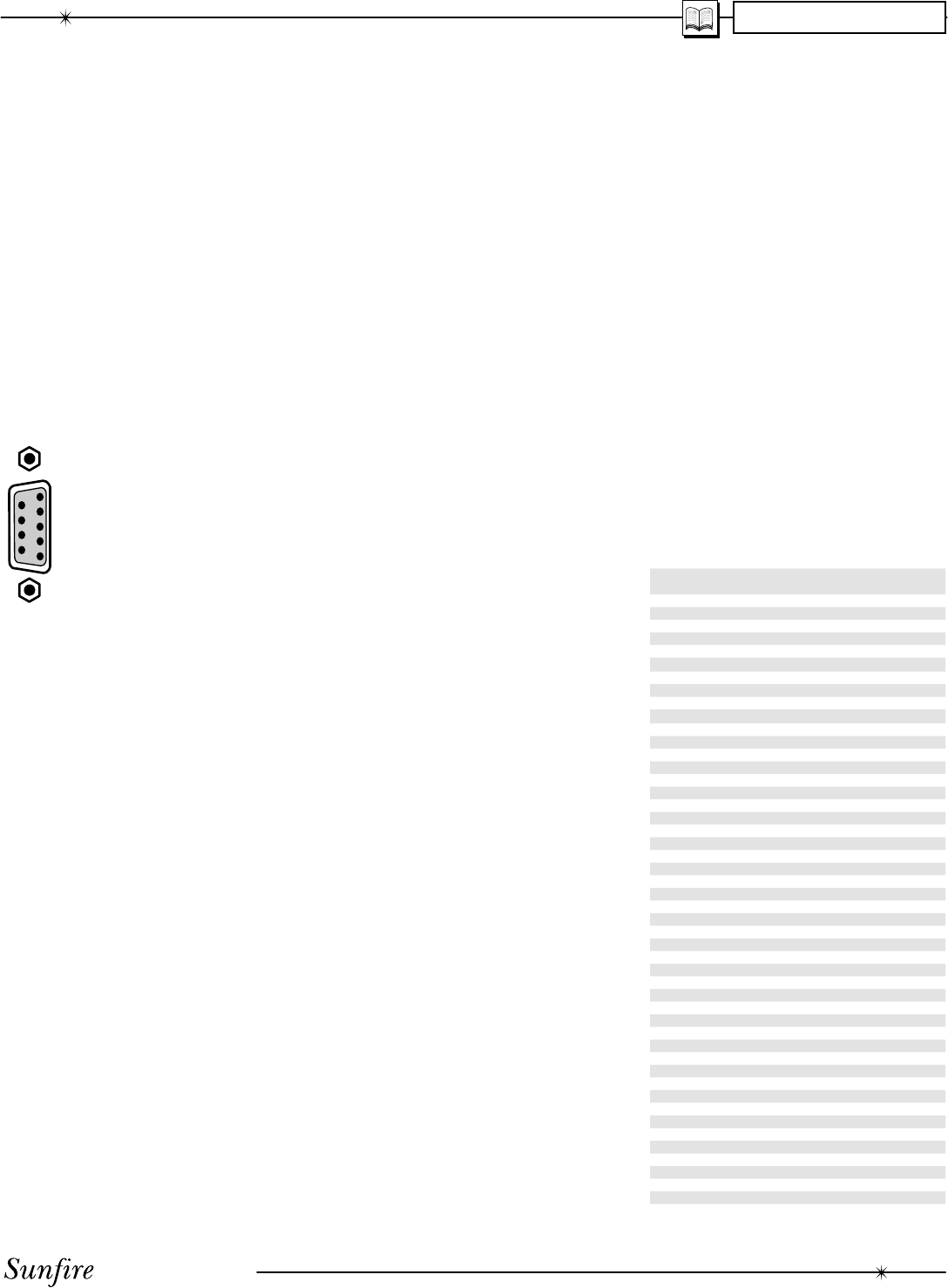
DB-9 Wiring
PINS 1, 6 and 4 are joined
together in ter nal ly
PINS 7 and 8 are joined to-
gether in ter nal ly
PIN 2- Data from processor to
controller (processor transmit)
PIN 3- Data from controller to
processor (processor receive)
PIN 5- Ground/Common
PIN 9- No connection
The RS-232 connector is female.
Serial Cable
To connect the Receiver's RS-232
port to a computer, you will need a
"straight-through" serial cable. This
has connector pins at one end con-
nected directly to the pins of the con-
nector at the other end. For example,
pin 1 at one end connects to pin 1 at
the other end, pin 2 connects to pin 2,
pin 3 to pin 3 and so on.
These common cables are avail-
able from most computer stores (or
from Radio Shack as # 26-117). It
should be 9-pin male at one end,
to Þ t into the Receiver and normally
9-pin female at the other, to Þ t into
your computer's serial port (COM1 or
COM2).
External Control
The RS-232 port also allows the
Receiver to be controlled externally by
Home Theater controllers and com-
put ers.
The following information is for
programmers and developers:
Partial Serial command set
Note that all stan dard com mands
and ex tend ed data are echoed back to
the sender. When a change is made
locally, the data is broad cast, except
for the case of “Toggle” and volume
commands. Here is a list of the most
popular commands. (Contact SunÞ re
Technical Support, or our website
www.sunÞ re.com for a more extensive
list of commands).
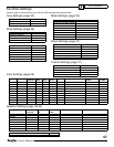
Update Procedure
1. The current version level of the
software running your Receiver
can be found by looking at the
Version Level OSD menu. This
is under the Software OSD
menu (see page 37).
2. If the website Þ le is newer than
your current version, follow the
website directions and down-
load the new Þ le onto your
computer's hard drive.
3. Record your calibration, preset
stations or other settings on
page 57. In most cases, the
upgrade will not affect any of
these settings, but it is good to
record them just in case.
4. Turn off your computer and the
Receiver. Position them close
enough so that they can be
easily connected using your
serial cable. If you have a lap-
top computer, then it may be
easier to bring that close to the
Receiver. Otherwise, you need
to disconnect the Receiver and
move it close to your computer.
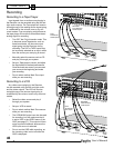
5. Connect the Receiver's RS-
232 port to the corresponding
serial port on your computer.
6. Turn on the Receiver and your
computer.
7. Find the Þ le you downloaded in
step 2, and run the program.
8. In AUTO mode, the software
will look for an active serial
connection and upload the new
Þ le. The Receiver's display will
show the status.
9. When the Þ le transfer is com-
plete, press the Power switch
on the Receiver's front panel.
This completes the upgrade.
10. Turn off your computer and the
Receiver, and disconnect the
serial cable.