


Page 21
Appendix
Appendix D - Calibration Information
The XLogic E Signature Channel unit is factory calibrated and should only need calibration if a potentiometer or
other component has been replaced or if it is suspected that there is a problem with calibration.
In all of the following instructions it is assumed that the lid has been removed and that power has been applied.
It is also assumed that unless otherwise specified, all switches are released and all potentiometers are at unity,
minimum or indent position as appropriate. The required accuracy for each adjustment will be specified along
with the target value.
All level and distortion measurements should be made with audio-band 20Hz to 20kHz filters unless otherwise
specified. All adjustments are made on the main (629612) card.
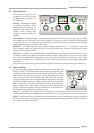
Line Input
Equipment Required: Calibrated audio oscillator and audio level meter
Test Signal: 1kHz sinewave @ +6dBu
Input and Output: Oscillator to Line Input and TP46 on the 629612 card to the audio level meter
Unit Setup: Set the Line Gain to indent (0dB)
Level Trim
Adjustment: 1. Adjust VR2 for 0dBu ±0.05dB.
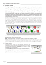
Output Stage
Equipment Required: Calibrated audio oscillator, audio level meter and dc. volt meter. A ‘balance’
adaptor (see below) will be required for the output balance adjustment.
Test Signal: 1kHz sinewave @ 0dBu
Input and Output: Oscillator to Line Input and Output to the audio level meter
Unit Setup: 1. Set both Line Gain and Output Gain to indent (0dB).
2. Press LINE switch IN.
Unity Gain Trim
Adjustment: 1. Adjust VR28 for 0dBu ±0.05dB.
DC Offset Trim
Adjustment: 1. Turn Oscillator off.
2. Measure on TP54 and adjust VR29 for 0V ±1mV.
3. Measure on TP59 and adjust VR30 for 0V ±1mV.
Output Balance
Input and Output: Signal source as before, connect the Output to the audio level meter via the
‘balance’ adaptor
Adjustment: 1. Adjust VR31 for minimum level (< 55dBr).
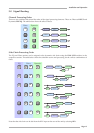
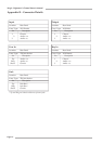
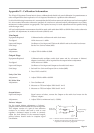
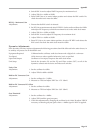
‘Balance’ Adaptor
For the output balance adjustment, a ‘balance’
adaptor such as that illustrated here will be required.
This adaptor consists of a pair of close tolerance
resistors in an in-line cable and is used to sum
together a balanced output in order to correctly
adjust the level balance of the measured output;
perfect balance should result in complete signal
cancellation.
5K01**
5K01**
2
3
1
2
3
1
0V
+
–
0V
+
–
To measuring
equipment
From unit
under test
1
2
1
Resistor tolerence should ideally be 0.01%
Absolute level measured will depend upon the input
impedence of the measuring equipment.
1.
2.
Note