


Page 11
Installation and Operation
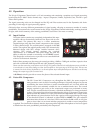
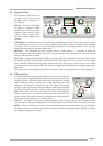
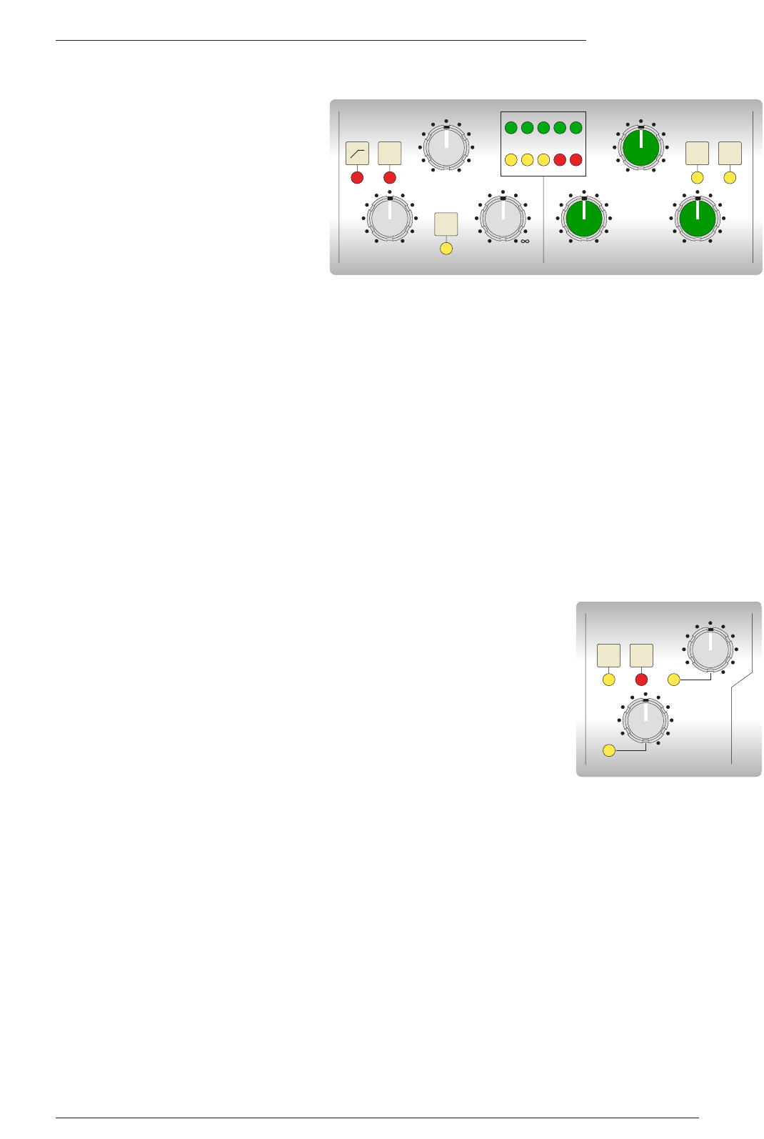
4.5 Expander/Gate
The Expander/Gate section can
act either as a
∞
:1 Gate or, when
the EXP switch is pressed, as a
2:1 Expander.
RANGE – Determines the depth
of gating or expansion. When
turned fully anti-clockwise, the
Expander/Gate section will be
inactive. When turned fully
clockwise, a range of 40dB can be
obtained.
THRESHOLD – Variable hysteresis is incorporated in the threshold circuitry. For any given ‘open’ setting,
the Expander/Gate will have a lower ‘close’ threshold. The hysteresis value is increased as the threshold
is lowered. This is very useful in music recording as it allows instruments to decay below the open
threshold before gating or expansion takes place.
RELEASE – This determines the time constant (speed), variable from 0.1 – 4 seconds, at which the
Gate/Expander reduces the signal level once it has passed below the threshold. Note that this control
interacts with the Range control.
FAST ATT – Provides a fast attack time (100µs per 40db). When off, a controlled linear attack time of 1.5ms
per 40dB is selected. The attack time is the time taken for the Expander/Gate to ‘recover’ once the signal
level is above the threshold. When gating signals with a steep rising edge, such as drums, a slow attack
may effectively mask the initial ‘THWACK’, so you should be aware of this when selecting the appropriate
attack time.
The green LEDs in the display section indicate Expander/Gate activity (the amount of gain reduction).
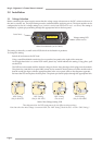
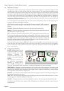
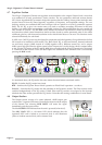
4.6 Filters Section
In common with the original E Series Channel strip, a pair of high- and
low-pass Filters are provided. Both Filter controls incorporate bypass
switching which is activated when turned fully anti-clockwise; turning
either control up will put that band in circuit, illuminating the LED
adjacent to the control to indicate this state. The Filters are normally
placed post- the EQ but can be routed to different audio paths within the
module. Both Filters normally exhibit a 12dB/octave but pressing the
BLK switch in the EQ section will modify the slope of the high-pass
Filter to 18dB/octave – see Section 4.7 overleaf for more detail on this
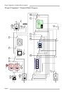
switch. Section 5 describes the routing combinations in more detail but,
briefly, these buttons function as described below.
DYN SC – The Filters are switched into the sidechain of the Dynamics section. The Equaliser can be
switched into the sidechain independently. Note that DYN SC overrides the INPUT function (see below).
INPUT – Moves the Filters to put them in circuit immediately post the Channel Input section. This allows
the Filters to be used to clean up signals before compressing them. Selecting Dynamics ‘PRE EQ’ will allow
the compressed signal to be EQ’d.
FILTERS
KHz
Hz
OUT 350
30020
200
70
OUT 3
3.512
4
8
DYN
S/C
INPUT
RELEASE
COMPRESSOR GATE
3 6 10 14 20
RATIO RELEASE RANGE
T/HOLD T/HOLD
.1 4 1 .1 4 0 40
0
-20+10
0
+10-30
FAST
ATK
LIN
REL
FAST
ATK
EXP