


Page 6
XLogic E Signature™ Channel Owner’s Manual
3.0 Installation
3.1 Voltage Selection
Before connecting the mains supply ensure that the voltage range selector next to the IEC socket on the rear of
the unit is correctly set. The input setting must be confirmed before applying power. The input module can be
configured to be one of 4 voltage settings (one of which is invalid and should not be used – see below). The setting is
indicated by a plastic pin protruding through the appropriate hole in the fuse panel.
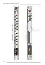
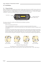
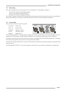
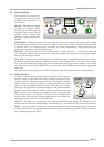
Mains Inlet Module (set for ‘240V’)
The setting is altered by a small vertical PCB which can be fitted in 4 positions.
To change the setting:
Switch off and remove the IEC lead.
Using a small flat-bladed screwdriver, lever open the fuse panel to the right of the connector.
At the right hand side is a vertical PCB with a plastic key which indicates the setting. Using pliers, pull
out the PCB.
The PCB has to be rotated until the desired voltage is shown along the edge which plugs into the module.
The plastic key (and this bit is quite fiddly) must also be rotated so that it points out of the module and so
that the round pin aligns with the appropriate hole in the cover panel; (refer to the diagrams opposite).
Re-insert the PCB and replace the fuse panel. The plastic pin should project through the appropriate hole.
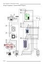
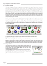
100V Setting 120V Setting 230V Setting 240V Setting
(Use for 90-105V) (Use for 105-125V) (Do not use) (Use for 220-240V)
Mains Inlet Voltage Setting PCB
These diagrams show the PCB arrangements for the different voltage settings.
Note that where the mains voltage is a nominal 230V, the ‘240V Setting’ should be used – not the ‘230V Setting’!
240
120
100
230
240
120
100
230
240
120
100
230
240
120
100
230
110V
120V
230V
240V
DISCONNECT POWER
BEFORE REPLACING FUSES
Before Connecting to
the supply, see the
Installation Instructions.
Lever here…
Voltage setting PCB
(under cover)