


33
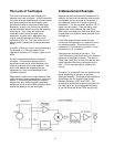
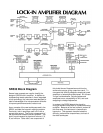
The Signal Channel
The instrument has both current and voltage
inputs. The current input is a virtual ground, and
the 100 MΩ voltage inputs can be used as single-
ended or true differential inputs.
There are three signal filters. Each of these filters
may be switched 'in' or 'out' by the user. The first
filter is a line notch filter. Set to either 50 or 60 Hz,
this filter provides 50 dB of rejection at the line
frequency. The second filter provides 50 dB of
rejection at the first harmonic of the line frequency.
The third filter is an auto-tracking bandpass filter
with a center frequency tuned by the micro-
processor to the frequency of the signal. These
three filters eliminate most of the noise from the
signal input before the signal is amplified.
A high-gain ac amplifier is used to amplify the
signal before entering the phase sensitive
detector. The high gain which is available from
this programmable amplifier allows the lock-in to
operate with a lower gain in its dc amplifier. This
arrangement allows high stability operation even
when used on the most sensitive ranges.
Reference Channel
The processor controlled reference input
discriminator can lock the instrument's PLL to a
variety of reference signals. The PLL can lock to
sine waves or to logic pulses with virtually no
phase error. The PLL outputs are phase shifted
and shaped to provide two precision sine waves.
The two sine waves have 90° of phase shift
between them.
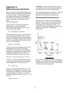
Phase Sensitive Detectors
The Phase Sensitive Detectors are linear
multipliers which mix the amplified and filtered
signal with the reference sine waves. The
difference frequency component of the multipliers'
outputs are dc signals that are proportional to the
amplitude of the signal. The low-pass filters which
follow each multiplier can reject any frequency
components which are more than a fraction of a
Hertz away from the signal frequency.
DC Amplifiers and System Gain
Dc amplifiers amplify and offset the outputs of the
two low pass filters. The total system gain is the
product of the ac and dc amplifier gains. The
partitioning of the system gain between these ac
and dc amplifiers will affect the stability and
dynamic reserve of the instrument. The output is
most stable when most of the gain is in the ac
amplifier, however, high ac gain reduces the
dynamic reserve.
For the most demanding applications, the user
may specify how the system gain is partitioned.
However, with prefilters that are able to provide up
to 100 dB of dynamic reserve, and with chopper
stabilized dc amplifiers, most users will not be
concerned with just how the system gain is
allocated.
A Microprocessor Based Design
The instrument was designed to take full
advantage of its microprocessor controller. This
approach provides several key advantages...
The instrument may be interfaced to a laboratory
computer over the RS232 and IEEE-488
interfaces. In addition to simply reading data from
the lock-in, the computer can control all of the
instrument settings with simple ASCII commands.
A key feature of the instrument is its four A/D
inputs and two D/A outputs. These analog I/O
ports may be used to read and supply analog
voltages to an experiment or measurement. All of
the input and output ports have a full-scale range
of ±10.24VDC with 2.5 mV resolution and 0.05%
accuracy.
Computer control can eliminate set-up errors,
reduce tedium, allow more complete data
recording and post measurement analysis. Also,
the computer can play an active role in the data
acquisition by adjusting gains, etc., in response to
changing measurement conditions.
The microprocessor based design eliminates
many analog components to improve
performance, reliability, and reduce cost. For
example, the magnitude and phase outputs are
calculated by the microprocessor instead of using
an analog vector summer. This eliminates the
temperature drifts and inaccuracies associated
with nonlinear analog circuits and greatly reduces
the number of parts. Each unit is computer
calibrated at the factory, and calibration constants
are placed in the instrument's read-only memory.
The SR530 has only one-fifth of the analog
trimming components that are found in older
designs.