


7
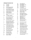
Abridged Command List
AX Auto offset X
AY Auto offset Y
AR Auto offset R
AP Auto phase
B Return Bandpass Filter Status
B0 Take out the Bandpass Filter
B1 Put in the Bandpass Filter
C Return the Reference LCD Status
C0 Display the Reference Frequency
C1 Display the Reference Phase Shift
D Return Dynamic Reserve Setting
D0 Set DR to LOW range
D1 Set DR to NORM range
D2 Set DR to HIGH range
En Return Channel n (1 or 2) Expand
Status
En,0 Turn Channel n Expand off
En,1 Turn Channel n Expand on
F Return the Reference Frequency
G Return the Sensitivity Setting
G1 Select 10 nV Full-Scale
... (G1-G3 with SRS preamp only)
G24 Select 500 mV Full-Scale
H Return Preamp Status (1=installed)
I Return the Remote/Local Status
I0 Select Local: Front panel active
I1 Select Remote: Front panel inactive
I2 Select Remote with full lock-out
J Set RS232 End-of-Record to <cr>
Jn,m,o,p Set End-of-record to n,m,o,p
K1 Simulates Key-press of button #1
... (see un-abridged command list)
K32 Simulates Key-press of button #32
L1 Return Status of Line Notch Filter
L1,0 Remove Line Notch Filter
L1,1 Insert Line Notch Filter
L2 Return Status of 2XLine Filter
L2,0 Remove 2XLine Notch Filter
L2,1 Insert 2XLine Notch Filter
M Return the f/2f Status
M0 Set reference mode to f
M1 Set reference mode to 2f
N Return the ENBW setting
N0 Select 1 Hz ENBW
N1 Select 10 Hz ENBW
OX Return X Offset Status
OX 0 Turn off X Offset
OX 1,v Turn on X Offset, v = offset
OY Return Y Offset Status
OY 0 Turn off Y Offset
OY 1,v Turn on Y Offset, v = offset
OR Return R Offset Status
OR 0 Turn off R Offset
OR 1,v Turn on R Offset, v = offset
P Return the Phase Setting
Pv Set the Phase to v. Abs(v) <999 deg
Q1 Return the Channel 1 output
Q2 Return the Channel 2 output
QX Return the X Output
QY Return the Y Output
R Return the trigger mode
R0 Set the trigger for rising edge
R1 Set the trigger for + zero crossing
R2 Set the trigger for falling edge
S Return the display status
S0 Display X and Y
S1 Display X and Y Offsets
S2 Display R and Ø
S3 Display R Offset and Ø
S4 Display X and Y noise
S5 Display X5 and X6 (ext D/A)
T1 Return pre-filter setting
T1,1 Set the pre-filter TC to 1 mS
...
T1,11 Set the pre-filter TC to 100 S
T2 Return the post-filter setting
T2,0 Remove post filter
T2,1 Set the post filter TC to 0.1 S
T2,2 Set the post filter TC to 1.0 S
V Return the value of the SRQ mask
Vn Set the SRQ Mask to the value n
(See the Status Byte definition)
W Return the RS232 wait interval
Wn Set RS232 wait interval to nX4mS
Xn Return the voltage at the rear panel
analog port n. (n from 1 to 6)
X5,v Set analog port 5 to voltage v
X6,v Set analog port 6 to voltage v
Y Return the Status Byte value
Yn Test bit n of the Status Byte
Z Reset to default settings and cancel
all pending commands.