29
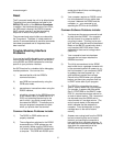
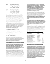
Vpsd1 = V
s
cos(w
r
t) cos(w
s
t+Ø)
= 1/2 V
s
cos[(w
r
+ w
s
)t+Ø] +
1/2 V
s
cos[(w
r
- w
s
)t+Ø]
Vpsd2 = Vs sin(w
r
t) cos(w
s
t+Ø)
= 1/2 V
s
sin[(w
r
+ w
s
)t+Ø] +
1/2 V
s
sin[(w
r
- w
s
)t+Ø]
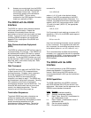
The sum frequency component of each PSD is
attenuated by a low pass filter, and only those
difference frequency components within the low
pass filter's narrow bandwidth will pass through to
the dc amplifiers. Since the low pass filter can
have time constants up to 100 seconds, the lock-in
can reject noise which is more than .0025 Hz
away from the reference frequency input.
For signals which are in phase with the reference
(¯=0¡), the output of PSD1 will be a maximum and
the output of PSD2 will be zero. If the phase is
non-zero, Vpsd1 ~ cos(Ø) and Vpsd2 ~ sin(°).
The magnitude output is given by,
R = {(V
psd1
)2 + (V
psd2
)
2
}
1/2
~ V
s
and is independent of the phase Ø. The phase
output is defined as
Ø = - tan
-1
(V
psd2
/ V
psd1
)
Thus, a dual-phase lock-in can measure the
amplitude of the signal, independent of the phase,
as well as measure an unknown phase shift
between the signal and the reference.
Understanding the Specifications
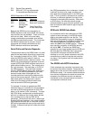
The table below lists some specifications for the
SR530 lock-in amplifier. Also listed are the error
contributions due to each of these items. The
specifications will allow a measurement with a 2%
accuracy to be made in one minute.
We have chosen a reference frequency of 5 kHz
so as to be in a relatively quiet part of the noise
spectrum. This frequency is high enough to avoid
low frequency '1/f' noise as well as line noise. The
frequency is low enough to avoid phase shifts and
amplitude errors due to the RC time constant of
the source impedance and the cable capacitance.
The full-scale sensitivity of 100 nV matches the
expected signal from our sample. The sensitivity
is calibrated to 1%. The instrument's output
stability also affects the measurement accuracy.
For the required dynamic reserve, the output
stability is 0.1%/°C. For a 10°C temperature
change we can expect a 1% error.
A front-end noise of 7 nV/√Hz will manifest itself
as a 1.2 nVrms noise after a 10 second low-pass
filter since the equivalent noise bandwidth of a
single pole filter is 1/4RC. The output will
converge exponentially to the final value with a 10-
second time constant. If we wait 50 seconds, the
output will have come to within 0.7% of its final
value.
The dynamic reserve of 60 dB is required by our
expectation that the noise will be a thousand times
larger than the signal. Additional dynamic reserve
is available by using the bandpass and notch
filters.
A phase-shift error of the PLL tracking circuits will
cause a measurement error equal to the cosine of
the phase shift error. The SR530's 1° phase
accuracy will not make a significant contribution to
the measurement error.
Specifications for the Example Measurement
Specification Value Error
Full Scale Sensitivity 100 nV
Dynamic Reserve 60 dB
Reference Frequency 5 kHz
Gain Accuracy 1% 1%
Output Stability 0.1%/°C 1%
Front-End Noise < 7 nV/√Hz 1.2%
Output Time Constant > 10 S 0.7%
Total RMS Error 2%
Shielding and Ground Loops
In order to achieve the 2% accuracy given in this
measurement example, we will have to be careful
to minimize the various noise sources which can
be found in the laboratory. (See Appendix A for a
brief discussion on noise sources and shielding)
While intrinsic noise (Johnson noise, 1/f noise and
alike) is not a problem in this measurement, other
noise sources could be a problem. These noise
sources can be reduced by proper shielding.
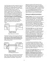
There are two methods for connecting the lock-in
to the experiment: the first method is more
convenient, but the second eliminates spurious
pick-up more effectively.


