


28
The Lock-in Technique
The Lock-in technique is used to detect and
measure very small ac signals. A Lock-in amplifier
can make accurate measurements of small signals
even when the signals are obscured by noise
sources which may be a thousand times larger.
Essentially, a lock-in is a filter with an arbitrarily
narrow bandwidth which is tuned to the frequency
of the signal. Such a filter will reject most
unwanted noise to allow the signal to be
measured. A typical lock-in application may
require a center frequency of 10 KHz and a
bandwidth of 0.01 Hz. This 'filter' has a Q of 10
6
-
well beyond the capabilities of passive electronic
filters.
In addition to filtering, a lock-in also provides gain.
For example, a 10 nanovolt signal can be
amplified to produce a 10 V output--a gain of one
billion.
All lock-in measurements share a few basic
principles. The technique requires that the
experiment be excited at a fixed frequency in a
relatively quiet part of the noise spectrum. The
lock-in then detects the response from the
experiment in a very narrow bandwidth at the
excitation frequency.
Applications include low level light detection, Hall
probe and strain gauge measurement, micro-ohm
meters, C-V testing in semiconductor research,
electron spin and nuclear magnetic resonance
studies, as well as a host of other situations which
require the detection of small ac signals.
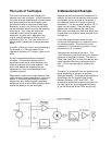
A Measurement Example
Suppose we wish to measure the resistance of a
material, and we have the restriction that we must
not dissipate very much power in the sample. If
the resistance is about 0.1Ω and the current is
restricted to 1 µA, then we would expect a 100 nV
signal from the resistor. There are many noise
signals which would obscure this small signal --
60Hz noise could easily be 1000 times larger, and
dc potentials from dissimilar metal junctions could
be larger still.
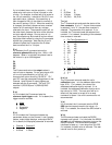
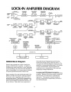
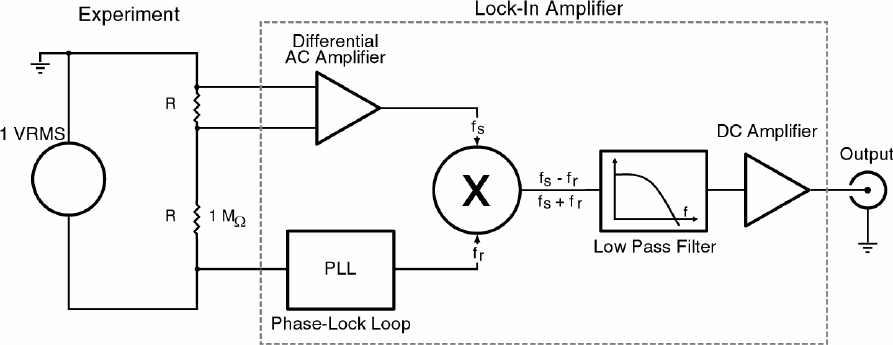
In the block diagram shown below we use a
1Vrms sine wave generator at a frequency w
r
as
our reference source. This source is current
limited by the 1 MΩ resistor to provide a 1 µA ac
excitation to our 0.1Ω sample.
Two signals are provided to the lock-in. The
1VAC reference is used to tell the lock-in the exact
frequency of the signal of interest. The lock-in's
Phase-Lock Loop (PLL) circuits will track this input
signal frequency without any adjustment by the
user. The PLL has two outputs, cos(w
r
t) and
sin(w
r
t).
The signal, Vs cos(w
s
t+Ø), from the sample under
test is amplified by a high gain ac coupled
differential amplifier. The output of this amplifier is
multiplied by the PLL outputs in two Phase-
Sensitive Detectors (PSD1 and PSD2). This
multiplication shifts each frequency component of
the input signal, w
s
, by the reference frequency,
w
r
, so that the output of the PSD's are given by: