14
down, the offset advances in larger and larger
increments, the largest increment being 10% of full
scale. When the offset is turned OFF the applied
offset returns to zero but the offset value is not
lost. The next press of the upper offset key (return
to ON) sets the offset to the previously entered
value.
If an attempt is made to advance the offset value
beyond full scale, the ON LED will blink. An offset
up to 1.024 times the full-scale sensitivity may be
entered. When the EXPAND is on, this is 10X the
full scale output.
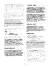
Note that the offsets (either manual offset or those
generated by the REL function) represent a
fraction of the full scale reading, and so their
absolute value will change when the sensitivity
scale is changed. A signal which has been nulled
by an offset will not be nulled when the sensitivity
scale is changed. The analog meter and the
output BNC indicate the same value given by the
equation:
V
out
= 10A
e
(A
v
V
i
sinØ+V
os
) {if the output is Y}
where...
A
e
= 1 or 10 per the Expand
A
v
= 1/Sensitivity
V
i
= magnitude of the signal
Ø = phase between signal & reference
V
os
= offset (fraction of FS < 1.024)
When the DISPLAY is Y, Y OFST, or Y NOISE,
the OFFSET keys adjust the Y OFFSET (which
affects the Y (RSINØ) output). When the
DISPLAY is Ø, the OFFSET keys do nothing.
When the DISPLAY is X6, the OFFSET up and
down keys set the output voltage of D/A output X6
(also on the rear panel) up to ±10.24V.
Expand Channel 2
The output EXPAND is toggled by pressing the
key in the Channel 2 EXPAND section. The
expand status is indicated by the X10, expand on,
and the X1, expand off, LED's. Only the Channel
2 OUTPUT is affected, the Y (RSINØ) output is
not expanded. Ø and X6 may not be expanded.
Y (RSINØ) Output
The analog output, Y+Y
ofst
, is available at the Y
(RSINØ) BNC connector. An input signal equal in
magnitude to the selected sensitivity which is 90°
out of phase with the reference oscillator will
generate a 10V output. The output impedance is
<1Ω and the output current is limited to 20 mA.
The Y (RSINØ) output is affected by the Y offset
but may not be expanded. The Y (RSINØ) is not
affected by the DISPLAY setting except for two
cases. When the DISPLAY is set to Y OFST, the
Y (RSINØ) output is the Y offset. When the
DISPLAY is set to Y NOISE, the Y (RSINØ) output
has a bandwidth equal to the ENBW (1 or 10 Hz)
instead of the time constant.
Reference Input
The REFERENCE INPUT BNC is located in
REFERENCE INPUT section. The input is ac
coupled and the impedance is 1 MΩ. The dc
voltage at this input should not exceed 100 V and
the largest ac signal should be less than 10 V
peak.
Trigger Level
The TRIGGER MODE indicator toggles from
POSITIVE to SYMMETRIC to NEGATIVE when
the TRIGGER MODE key is pressed.
If the center TRIGGER MODE LED is on, the
mode is SYMMETRIC and the reference oscillator
will lock to the positive zero crossings of the ac
reference input. The ac signal must be symmetric
(e.g. sine wave, square wave, etc.) and have a
peak to peak amplitude greater than 100 mV. A
signal with 1 Vrms amplitude is recommended.
The phase accuracy of the reference channel is
specified for a 1Vrms sinewave in the symmetric
trigger mode.
If the upper TRIGGER MODE LED is on, the
mode is POSITIVE. The trigger threshold is +1V
and the reference oscillator will lock to the positive
going transitions of the reference input. This
mode triggers on the rising edges of a TTL type
pulse train. The pulse width must be greater than
1 µS.
If the lower TRIGGER MODE LED is on, the mode
is NEGATIVE. The trigger threshold is -1V and
the reference oscillator will lock to the negative


