39
Appendix B:
Introduction to the RS232
The 'RS232' is a standard for bit serial
asynchronous data communication. The standard
defines the format for data transmission, the
electrical specifications for the signal levels, and
the mechanical dimensions of connectors.
Despite the definition of a standard, there are so
many permutations of control lines, data formats,
and transmission speeds, that getting two RS232
devices to communicate usually requires some
work.
In this section, we will provide some basic
information to aid you in connecting your RS232
device to the SR510 Computer Interface.
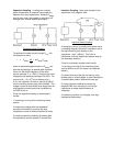
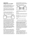
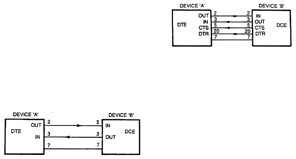
CASE 1 - The Simplest Configuration.
In this case, one wire is used to send data from
device A to device B and another wire is used to
send data from device B to device A. Notice that
pin 2 is an output on device A and an input on
device B. (It is good practice to run the ground,
pin 7, between the devices as well). The RS232
defines two types of devices; DTE (Data Terminal
Equipment) and DCE (Data Communications
Equipment.) An RS232 port on a computer may
be either a DTE or DCE but nearly every terminal
with an RS232 port is a DTE. RS232 ports on a
computer which are intended to connect to a
modem, such as the COM1: port on the IBM PC,
are DTE. The SR530 is configured as DCE, and
so it may be directly connected to ASCII terminals
and to the COM: ports on IBM PC's and
compatibles.
As an example, consider connecting an RS232
ASCII computer terminal to the SR510 using a 2
wire link. The terminal is a DTE and the SR510 is
a DCE. To operate correctly, the SR510 and the
terminal must have the same settings for baud
rate, parity, and number of stop bits. The control
lines in the RS232 Standard, which are used to
indicate that a device is ready to accept data, must
also be connected correctly at the terminal end. If
the terminal responds to a control line, it will
believe that the SR510 is not ready to accept data
(because the line is not passed in this example)
and will therefore not send any data.
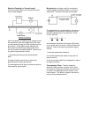
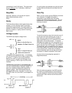
CASE 2 - RS232 with Control Lines.
The data lines are the same as in Case 1. In
addition to the data lines, there are two control
lines used:
CTS - Pin 5
"Clear to send" is a signal asserted by the DCE to
tell the DTE that the DCE is ready to receive data.
DTR - Pin 20
"Data Terminal Ready" is a signal asserted by the
DTE to tell the DCE that the DTE is ready to
receive data.
The SR510 responds to the control lines as
follows:
1) If the lines are not connected, the SR510
assumes that you are ready to receive data.
2) Data will not be transmitted from the SR510 if
the DTR line (pin 20) is low. This is useful in the
case when your program is not yet ready to
receive data. If data transmission is not
suspended, then data may be overwritten in your
computer's UART (as it is not being retrieved by
the program and so will be lost.) When this
happens, the 'over-run' flag will be set in your
computer's UART and it may be recognized by the
operating system, generating an error message
such as "I/O Device Error" (See the "W" command
in the SR510 Command List for another way to
slow data transmission.)
Baud Rate
The RS232 baud rate of the SR510 is switch
selectable from 300 to 19.2K baud (see
configuration switch setting in the front of this
manual.) 19.2K baud means that data is
transmitted at 19,200 bits/second. With one start
bit, 2 stop bits, 8 data bits, and no parity bits, each
ASCII character requires 573 µsec to be


