


26
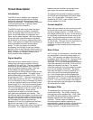
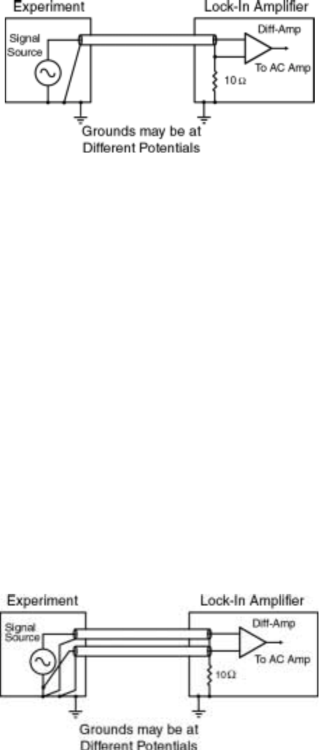
(as is the case here) the noise picked up by the
shield will also appear on the center conductor.
This is good, because the lock-in's 100 dB CMRR
will reject most of this common mode noise.
However, not all of the noise can be rejected,
especially the high frequency noise, and so the
lock-in may overload on the high sensitivity
ranges.
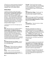
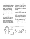
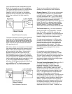
Quasi-Differential Connection
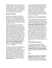
The second method of connecting the experiment
to the lock-in is called the 'true-differential' mode.
Here, the lock-in uses the difference between the
center conductors of the A & B inputs as the input
signal. Both of the signal sources are shielded
from spurious pick-up.
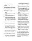
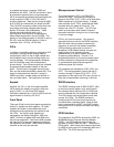
With either method, it is important to minimize both
the common mode noise and the common mode
signal. Notice that the signal source is held near
ground potential in both cases. A signal which
appears on both the A & B inputs will not be
perfectly cancelled: the common mode rejection
ratio (CMRR) specifies the degree of cancellation.
For low frequencies the CMRR of 100 dB indicates
that the common mode signal is canceled to 1 part
in 10
5
, but the CMRR decreases by about 6
dB/octave (20 dB/Decade) starting at 1KHz. Even
with a CMRR of 10
5
, a 10 mV common mode
signal behaves like 100nV differential signal.
True-Differential Connection
There are some additional considerations in
deciding how to operate the lock-in amplifier:
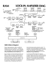
Dynamic Reserve (DR) is the ratio of the largest
noise signal that the lock-in can tolerate before
overload to the full scale input. Dynamic reserve
is usually expressed in dB. Thus a DR of 60 dB
means that a noise source 1000 times larger than
a full scale input can be present at the input
without affecting the measurement of the signal. A
higher DR results in a degraded output stability
since most of the gain is DC gain after the phase
sensitive detector. In general, the lowest DR
which does not cause an overload should be used.
The Current Input has a 1 kΩ input impedance
and a current gain of 10
6
Volts/Amp. Currents
from 500 nA down to 100 fA full scale can be
measured. The impedance of the signal source is
the most important factor to consider in deciding
between voltage and current measurements.
For high source impedances, (>1 MΩ) or small
currents, use the current input. Its relatively low
impedance greatly reduces the amplitude and
phase errors caused by the cable capacitance-
source impedance time constant. The cable
capacitance should still be kept small to minimize
the high frequency noise gain of the current
preamplifier.
For moderate source impedances or larger
currents, the voltage input is preferred. A small
value resistor may be used to shunt the source.
The lock-in then measures the voltage across this
resistor. Select the resistor value to keep the
source bias voltage small while providing enough
signal for the lock-in to measure.
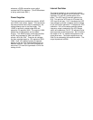
The Auto-Tracking Bandpass Filter has a Q of 5
and follows the reference frequency. The
passband is therefore 1/5 of the reference
frequency. The bandpass filter can provide an
additional 20 dB of dynamic reserve for noise
signals at frequencies outside the passband. The
filter also improves the harmonic rejection of the
lock-in. The second harmonic is attenuated an
additional 13dB and higher harmonics are
attenuated by 6 dB/octave more. You may wish to
use the bandpass filter and select a low dynamic
reserve setting in order to achieve a better output
stability. Since the processor can only set the
bandpass filter's center frequency to within 1% of
the reference frequency, this filter can contribute
up to 5° of phase shift error and up to 5% of
amplitude error when it is used. In addition, the