


11
EN
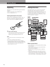
Getting Started
Basic Operations
Selecting a Component
To listen to or watch a connected component, first
select the function on the amplifier or with the remote.
Before you begin, make sure you have:
• Connected all components securely and correctly as
indicated on pages 5 to 9.
• Turned MASTER VOLUME to the leftmost position
(0) to avoid damaging your speakers.
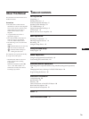
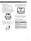
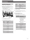
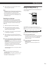
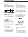
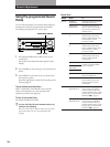
INPUT
MODE
VIDEO FUNCTION AUDIO FUNCTION
GENRE
TONE
SUR INDEX
SET UP
DIRECT
PASS
MODE
DIRECT PASS
SOUND FIELD
ON / OFF
BASS
BOOST
BALANCE
LR
STANDBY
DISCRETE
5
0
1
3
9
7
4
6
2
8
1
0
•
•
•
•
•
•
•
•
•
•
•
•
•
•
•
•
•
•
•
•
•
•
•
•
•
•
•
•
•
•
•
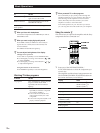
PHONES
POWER
SPEAKERS
DPC
MODE
A
OFF
A
+B
B
g
MASTER VOLUME
VIDEO 2VIDEO 1 VIDEO 3 LD TV TAPE DAT / MD CD TUNER PHONO
DISPLAYDIMMER
S VIDEO RLVIDEO AUDIO
VIDEO 3 INPUT
SET UPDIRECT PASS
VIDEO/AUDIO
FUNCTION
MASTER VOLUME
INPUT
MODE
BASS
BOOST
BALANCE
POWER
PHONES
DIMMER
SPEAKERS
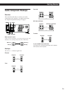
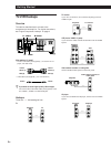
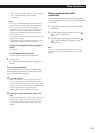
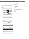
1 Press POWER to turn on the amplifier.
The STANDBY indicator turns off.
2 Select the component you want to use:
To watch or
listen to
To light up
VIDEO
FUNCTION
AUDIO
FUNCTION
VIDEO
FUNCTION
VIDEO
FUNCTION
AUDIO
FUNCTION
AUDIO
FUNCTION
AUDIO
FUNCTION
Press
(repeatedly)
3 Turn on the component, for example, a CD player,
and then start playing.
4 Turn MASTER VOLUME to adjust the volume.
To adjust the volume of the TV’s speakers, use the
volume control on the TV.
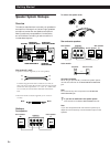
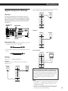
z To listen to digital program sources
Do the procedure below.
1 Do Steps 1 and 2 above to select the component.
2 Press INPUT MODE repeatedly to select input mode
for the component.
When you select The amplifier selects
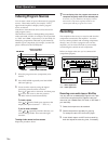
Digital processing control buttons
Basic Operations
Video tapes
Laser discs
TV programs
Audio tapes
Compact Discs (CD)
Radio programs
Records
VIDEO 1 or VIDEO 2
LD
TV
TAPE
CD
TUNER
PHONO
VIDEO
FUNCTION
Video camera
recorder or video
game
VIDEO 3
To watch or
listen to
To light upPress
(repeatedly)
AUTO INPUT
DIGITAL(AC-3 RF)*
DIGITAL
(COAXIAL)*
DIGITAL
(OPTICAL)
MiniDiscs (MD) or
Digital Audio Tapes
(DAT)
AUDIO
FUNCTION
DAT/MD
the component connected to the
following jack(s) depending on
the component selected in Step 1
above (listed in order of priority).
When you selected LD:
1 the AC-3 RF jack
2 the COAXIAL jack
3 the OPTICAL jack
4 the analog jacks
When you selected CD or DAT/
MD:
1 the OPTICAL jack
2 the analog jacks
the component connected to the
LD IN AC-3 RF jack
the component connected to the
COAXIAL jack
the component connected to the
OPTICAL jack
ANALOG INPUT the component connected to the
analog jacks
* Appears only when you selected LD in Step 1
(Continued)