


— 56 —
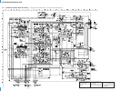
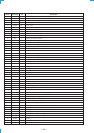
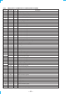
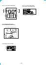
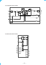
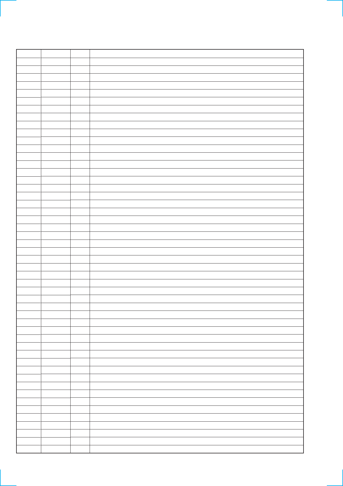
IC102 MB90553APF-G-138-BND DISPLAY CONTROL(DISPLAY BOARD)
Description
DCS logo display data output to LED.
EQ ON/OFF display data output to LED.
BASS BOOST display data output to LED.
MUTING display data output to LED.
DOLBY DIGITAL display data output to LED.
VOLUME display data output to LED.
Power reay display.
Power check (+5V)
Not used. (Connected to ground)
Not used. (Connected to ground)
Ground (Connected to ground)
Not used. (Connected to ground)
Not used. (Connected to ground)
Not used. (Connected to ground)
Not used. (Connected to ground)
Not used. (Connected to ground)
Not used. (Connected to ground)
Not used. (Connected to ground)
UART data output to rewrite flash memory
UART data intput to rewrite flash memory
Clock output to flourescent display tube
Data output to flourescent display tube
Power supply +5 V
Fluorescent latch
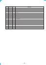
Fluorescent clear
SIRCS input
External power regulator capacitor 0.1µ is connected to this terminal.
Not used (Connected to ground)
Not used (Connected to ground)
Not used (Connected to ground)
Not used (Connected to ground)
Not used (Connected to ground)
Not used (Connected to ground)
Analog power supply +5 V
AVRH (Connected to power supply +5 V)
SVRL (Connected to ground)
Ground (Connected to ground)
Key input 1
Key input 2
Key input 3
Key input 4
Ground (Connected to ground)
Key input 5
Key input 6
Key input 7
RDS signal input.
Stop input
Not used (Connected to ground)
MD 0 (To MD0 of MB90573)
MD 1 (Connected to power supply +5 V)
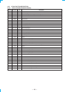
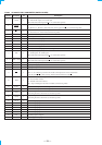
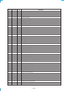
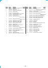
Pin No.
1
2
3
4
5
6
7
8
9
10
11
12
13
14
15
16
17
18
19
20
21
22
23
24
25
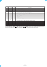
26
27
28
29
30
31
32
33
34
35
36
37
38
39
40
41
42
43
44
45
46
47
48
49
50
I/OPin Name
DCS
EQ
B.B
MUTE
D.D
VOLUME
POWER RY
5V CHECK
—
—
VSS
—
—
—
—
—
—
—
SOT0
SIN0
FL CLK
FL DATA
VCC
FL LAT
FL CLEAR
SIRCS IN
C
—
—
—
—
—
—
AVCC
AVRH
AVRL
AVSS
AD KEY IN 1
AD KEY IN 2
AD KEY IN 3
AD KEY IN 4
VSS
AD KEY IN 5
AD KEY IN 6
AD KEY IN 7
RDS SIGNAL
STOP
—
MD 0
MD 1
O
O
O
O
O
O
O
O
—
—
—
—
—
—
—
—
—
—
O
I
O
O
—
O
O
I
—
—
—
—
—
—
—
—
—
—
—
I
I
I
I
—
I
I
I
I
I
—
I
I