


— 52 —
51
52
53
54
55
56
57
58
59
60
61
62
63
64
65
66
67
68
69
70
71
72
73
74
75
76
77
78
79
80
81
82
83
84
85
86
87
88
89
90
91
92
93
94
95
96
97
98
99
100
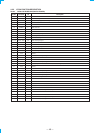
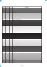
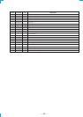
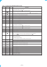
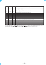
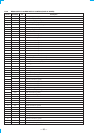
I/O DescriptionPin Name
SLVDTA/REQ
DISPCLK
N.C
VCC
S.LAT
S.DATA
S.CLK
DATA IN
AUSTOP
STEREO
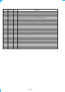
N.C
N.C
VSS
N.C
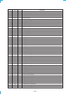
TH
PROTEC
STOP
N.C
N.C
N.C
N.C
VIDEO(SW4)
X1A
X0A
VIDEO(SW3)
VIDEO(SW2)
VIDEO(SW1)
DIGITAL 1/4
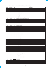
TAPE NO/ YES
VIDEO3 NO/ YES
DTS NO/ YES
ACMUTE
96K NO/YES
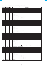
T.MUTE
S.MUTE
HSTX
MD2
MD1
MD0
REST
VSS
XO
XI
VCC
PO0
PO1
RY-4/B
RY-PRE
RY-FRONT/A
RY-FRONT/B
O
I
I
—
O
O
O
I
I
I
I
I
—
I
I
I
I
I
I
I
I
O
—
—
O
O
O
I
I
I
I
O
I
O
O
—
—
—
—
I
—
—
—
—
I
I
O
O
O
O
Slave data/request (Connected to MCU U.SREQ)
Display clock (Connected to MCU U.CLOCK)
Not used (Connected to ground)
Power supply +5 V
To tuner latch
To tuner data
To tuner clock
PLL data in
Auto stop input
Stereo input
Not used (Connected to ground)
Not used (Connected to ground)
Ground (Connected to ground)
Not used (Connected to ground)
TH Protector input
Protector input
AC power check
Not used (Connected to ground)
Not used (Connected to ground)
Not used (Connected to ground)
Not used (Connected to ground)
Video select SW4
Not used
Not used
Video select SW3
Video select SW2
Video select SW1
Digital function
Tape NO/YES input
I VIDEO3 NO/ YES input
DTS NO/ YES input
Power amp mute ON/OFF output
96K NO/YES input
Tuner muting
Surround muting (Connected to ground)
Hardware standby (Connected to power supply +5 V)
MD2 (To MCU MD2)
MD1 (Connect to power supply)
MD0 (To MCU MD0)
Reset (Connected to MB90553 U.RESET)
Ground (Connected to ground)
External ceramic filter 16MHz is connected to this terminal
External ceramic filter 16MHz is connected to this terminal
Power supply +5V
Flash memory rewrite (Connected to ground)
Flash memory rewrite (Connected to ground)
4/8 relay
Pre relay
Front speaker A relay
Front speaker B relay
Pin No.