


33
Connections and Settings
Chapter 2 Preparations
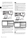
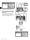
For details about the settings of the HDW-M2000/
M2000P, refer to the operation manual for that unit.
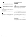
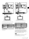
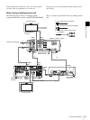
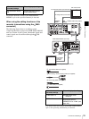
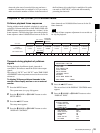
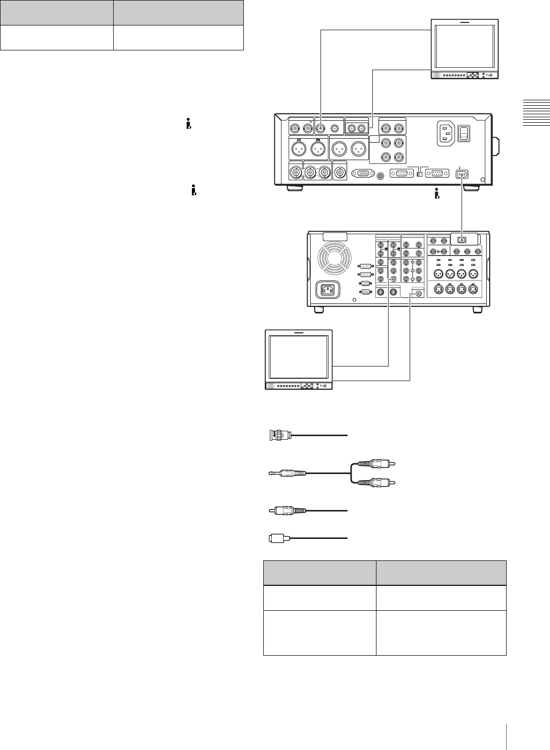
When using the editing functions of the
recorder (connections using the S400
connector)
The following figure shows a cut editing system
comprising this unit as a player and a DSR-2000A/2000AP
unit as a recorder. In this system, video/audio signals and
control signals are all transferred through the S400
connector.
For details about the settings of the DSR-2000A/2000AP,
refer to the operating instructions for that unit.
75Ω termination switch:
ON
Remote connector selector
switch: REMOTE(9P)
HDW-M2000/M2000P
(recorder) settings
This unit (player) settings
DSR-2000A/2000AP
(recorder) settings
This unit’s (player) settings
i.LINK button: Lit Remote control switch:
REMOTE
SDTI/i.LINK button: i.LINK Set the setup menu item
INTERFACE SELECT
>REMOTE I/F to “i.LINK” (see
page 103).
SDSDI OUTPUTHDSDI INPUT
AUDIO INPUT
HDSDI OUTPUT
12
REF VIDEO INPUT
TIME CODE
POWER
ANALOG HD INPUT
DIGITAL
AUDIO
(AES/EBU)
COMPOSITE OUTPUT AUDIO MONITOR
1/3 2/4
AUDIO OUTPUT
1/3 2/4
R L IN OUT
Y/G P
B /R
SYNS
RS232C REMOTE(9P)
PB /B
1/2
INPUT
OUTPUT
CONTROL
3/4
1/2 3/4
S400
MONITOR
-AC IN
MONITOR
AUDIO
i.LINK
VIDEO OUT 3
(SUPER)
S400
COMPOSITE
OUTPUT
AUDIO
MONITOR
To analog audio input connector
PDW-F75 (this unit, player)
1
2: Phono plug – stereo miniplug cable (not supplied)
3: Phono plug cable (not supplied)
To composite
video input
connector
DSR-2000A/2000AP (recorder)
SD video monitor
SD video monitor
To composite video input connector
To analog audio input connector
2
4
1: 75Ω coaxial cable (not supplied)
4: i.LINK cable (not supplied)
1
3