


18
MZ-NH700/NHF800
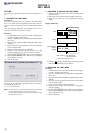
3-4-3. VBsAdj adjustments
Procedure:
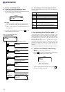
1. In the “3-4-2. PwrAdj Adjustments” completed status, press
the > key to display as follows.
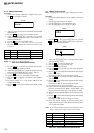
Display
2. Apply the voltage of 5 V to the CL453 (VBUS 5V) and CL460
(VBUS GND).
3. Press the > key to change the item number to 2241.
4. Adjust with [VOL+]/[VOL--] keys so that the value of digital
voltmeter becomes specification value. (refer to “table 3-4-2.
VBsAdj Specifications”)
5. Press the X key to write the adjusted value.
6. Press the > key to select the next item, and repeat
adjustments to item number 2243 at the same manner as step
3 to step 5.
Item No. Display Specification value Measuring point
2241 241 AD ** 1.13 V ± 0.01 V CL8001
2242 242 AD ** 2.05 V + 0.02 V CL8027
2243 243 AD ** 3.30 V ± 0.01 V CL8055
Note1: “**” is adjustment value (hexadecimal number).
Note2: Ground point of all adjustment points is CL433.
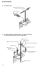
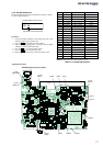
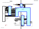
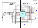
Note3: Refer to page 18 for adjustment location.
Table 3-4-2. VBsAdj Specifications
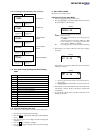
7. Press the > key to select the item number 2244, and turn
off the power supply of battery terminal.
8. Adjust with [VOL+]/[VOL--] keys so that the voltage of between
CL935 and CL433 (GND) becomes 1.80 V (− 0.02 V).
9. Press the X key to write the adjusted value.
10. Apply the voltage of 1.2 V to the battery terminal again.
11. Press the x key to display “240 VBsAdj” (Item number:
2240).
12. Turn off the voltage of 5 V to the CL453 (VBUS 5V) and
CL460 (VBUS GND).
13. Press the x key three times and back to the Display Check
mode.
240
VBsAdj
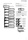
3-5. Charge Function Check
Note: When perform this check, don’t apply a voltage to battery terminals.
Procedure:
1. Connect the digital voltmeter to CL431 (BATT+) and CL433
(GND).
2. Enter the test mode using the AC adapter.
3. Press the [VOL+] key to enter the Manual mode.
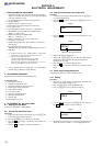
4. Press the [VOL+] key twice to display as follows.
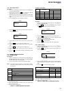
Display
5. Press the > key once, press the [VOL+] key once, press the
> key once, press the [VOL+] key three times, and press the
> key once to display as follows.
Display
6. Adjust with [VOL+]/[VOL--] keys so that the value of digital
voltmeter becomes 1.80 V.
7. Press the X key to write the adjusted value.
8. Press the > key to select the next item.
9. Disconnect the digital voltmeter.
10. Press the > key to select the next item (2262) and display
“262 AD CC”.
11. Press the X key and confirm that the adjustment value changes
from “CC” to “DD”.
If it changes to “BB”, IC401 (for charge IC) is fault.
12. Press the > key to select the next item (2263) and display
“263 AD CC”.
13. Press the X key and confirm that the adjustment value changes
from “CC” to “DD”.
If it changes to “BB”, IC401 (for charge IC) is fault.
14. Disconnect the power supply (AC adaptor).
15. Connect the resistor of the specified value (see table below) to
the battery terminals (CL431: BATT+, CL432: BATT−), and
then connect the AC adapter again, and enter the test mode.
16. Select item number 2264 through the operation similar to steps
2 to 8.
17. Press the X key and confirm that the adjustment value changes
from “CC” to “DD”.
If it changes to “BB”, IC401 (for charge IC) is fault.
18. In the same manner, exchange the resistors with the power
supply disconnected, and confirm that the adjustment value is
“CC” in each item number.
Note: Be sure to disconnect the AC adapter when exchanging the resistors.
Doing so with the power supply connected causes a trouble.
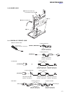
Item No. Display Connecting Resistor
2262 262 AD ** No resistor
2263 263 AD ** No resistor
2264 264 AD ** 22 Ω (0.1 watts or more)
2265 265 AD ** 10 Ω (1.0 watts or more)
2266 266 AD ** 10 Ω (1.0 watts or more)
2267 267 AD ** 2.2 Ω (1.5 watts or more)
Table 3-5-1. Charge Adjustment Specifications
2
POWER
261
AD **
adjustment value (hexadecimal)
Ver 1.1