


MZ-E10
9
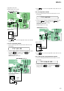
2. During each test, press and hold down
>
key or
.
key for a while to move the optical pickup on the sled outer or
inner perimeter.
3. Each test item is assigned with a three-digit item number. The
100th place is a major item, 10th place is a middle item, and unit
place is a minor item.
Note: Changes in adjustment item settings are written into the
non-volatile memory.
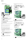
4-4. MANUAL MODE
4-4-1. Outline of the function
The Manual mode is designed to perform adjustments and
operational checks on the set’s operation according to each
individual function.
The Manual mode is used to clear the memory before
performing automatic adjustments in the Overall Adjustment mode.
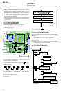
4-4-2. How to set the Manual mode
1. Set the TEST MODE and press
VOL +
key to set the Manual
mode.
Remote control LCD display
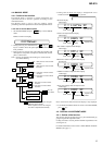
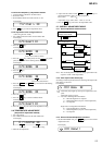
4. During each test mode, the display is changed from one to
another each time DISPLAY key is pressed.
000 Manual
Change Major
Item
Change Middle
Item
Change Minor
Item
Change Adjustment
Value
Write Adjustment
Value
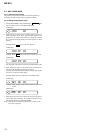
.
key : 100th place of mode number
increase
+
key : 100th place of mode number
decrease
key : 10th place of mode number
increase
key : 10th place of mode number
decrease
key : Up
key : Down
key : When adjusted value is changed :
Adjusted value is written.
When adjusted value is not changed :
That item is adjusted automatically.
keykey
x
key
x
>
key
>
key : Unit place of mode number
increase
key : Unit place of mode number
decrease
>
VOL
VOL
+
VOL
VOL
+
VOL
VOL
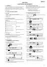
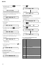
011 AAAS 3F
address
mode number
mode number
mode number
mode number
mode number
adjusted value
adjusted value
adjusted value
adjusted value
adjusted value
011 OFFJ 3F
jitter value
011 000B 3F
block error value
011 000A 3F
ADIP error value
011 000F 3F
Focus drive voltage value
• Address & Adjusted Value Display
LCD display
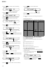
011 Lrefpw 3F
Item title
mode number
adjusted value
• Item title Display
LCD display
• Jitter Value & Adjusted Value Display
LCD display
• Block Error Value & Adjusted Value Display
LCD display
• ADIP Error Value & Adjusted Value Display
LCD display
• Focus drive voltage value & Adjusted value
LCD display
Note: In the Power mode, the item title display is only displayed.
5. To terminate the Manual mode and return to the TEST MODE,
press
x
key.
4-5. OVERALL ADJUSTMENT MODE
4-5-1. Outline of the function
This mode is designed to adjust the servo system automatically by
going through all the adjustment items.
Usually, this mode is used to perform automatic adjustments when
servicing the set.
For further information, refer to section 5. ELECTRICAL ADJUST-
MENTS. (See page 11)