


12
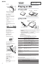
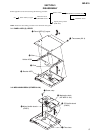
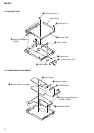
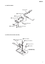
MZ-E10
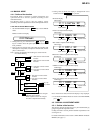
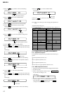
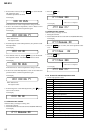
12.Press the key. (Address section starts flashing.)
LCD display
862 88D3 FC
This section (address) flashes.
13.Press the key to return to Manual mode.
LCD display
862 VarWrt 00
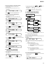
14.Press the key and write in the correction data.
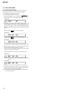
15. Press the
>
key and 862 as the item number.
LCD display
862 VarWrt 01
Data value.
16.Press the key, and set in Adjustment change mode.
LCD display
862 88C6 FF
This section (address) flashes.
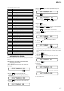
17. Press the
x
key . (FF section (data) flashes)
18.Press the
VOL +
and
VOL –
key and set the value in the
flashing data section while referring to the adjustment data change
list.
LCD display
862 88C6 07
Data value.
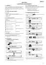
19.Press the key, and the address section starts flashing.
20.Press the
VOL +
key and set the next adjustment address.
LCD display
862 88C7 FF
This section (address) flashes.
21. Press the
x
key . (FF section (data) flashes)
LCD display
22.Press the
VOL +
and
VOL –
key and set the value in the
flashing data section while referring to the adjustment data change
list.
LCD display
862 88C7 8D
Data value.
23.Press the key, and the address section starts flashing.
24.Press the
key to return to Manual mode.
LCD display
862 VarWrt 01
Data value.
25.Press the key and write in the correction data.
26.Turn off the power.
Note: Always turn off the power after changing the adjustment set-
tings.
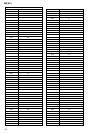
Adjustment Data Change List
If adjustment data is VarWrt is 00
Version 1.000
Address Adjustment Data
88C6 3F
88C7 03
88C8 D6
88C9 22
88CA C4
88CB 37
88CC C2
88CD 04
88CE E8
88CF 42
88D0 6E
88D1 FC
88D2 71
88D3 FC
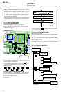
5-4. POWER SUPPLY VOLTAGE ADJUSTMENTS
5-4-1. Adjustment sequence
The adjustments should be always performed in the following se-
quence:
1 LEG1 adjustment (item No.:741)
r
2 VC1 adjustment (item No.:742)
r
3 VC2 adjustment (item No.:743)
r
4 Class-D power supply adjustment (item No.:744)
5-4-2. REG1 adjustment method
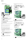
1. Supply power (DC 6.0 volts) from the charging terminal CN951.
2. Set the Test mode.
3. Set the overall adjustment mode and press
P.MODE/F
key, item No. will change to 741.
LCD display
741 Reg1 XX
4. Connect a digital voltmeter to TP908 (REG1) on the main
board and adjust
VOL +
(voltage up) key and
VOL –
(voltage down)key on the remote control.
If adjustment data is VarWrt is 01
Version 1.000
Address Adjustment Data
88C6 07
88C7 8D
88C8 FF
88C9 FF
88CA FF
88CB FF
88CC FF
88CD FF
88CE FF
88CF FF
88D0 FF
88D1 FF
88D2 FF
88D3 FF