


17
MZ-E10
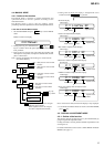
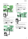
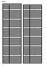
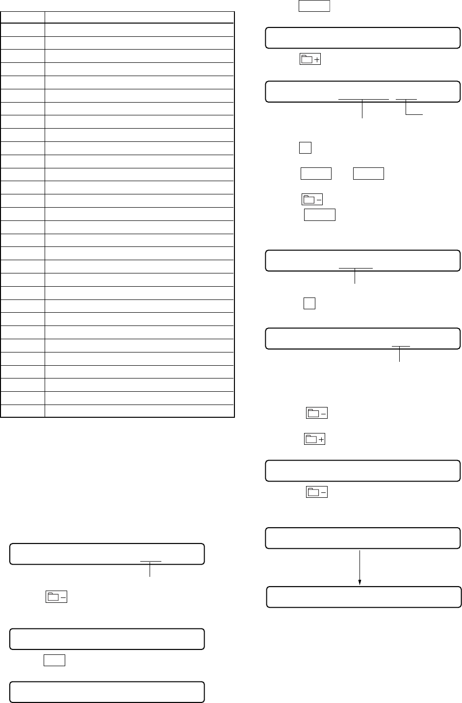
2. Overall MO adjustment items
Item No. Contents
112 ALFA offset adjustment
113 IJ offset adjustment
114 FE offset adjustment
118AW DW OFFSET
224 TE offset adjustment
221 TE gain adjustment
224 TE offset adjustment
236 ABCD gain adjustment
237 KF gain adjustment
238 RF gain adjustment
244 Focus gain adjustment
245 Tracking gain adjustment
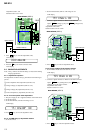
120 Focus servo ON
122 TE offset adjustment (TON)
121 TE gain adjustment
122 TE offset adjustment (TON)
123 TE offset adjustment (TEIN)
124 TE offset adjustment (TWPP)
130 Tracking servo ON
131 TE offset adjustment (TWPP/RF)
136 ABCD gain adjustment
137 KF gain adjustment
144 FCS gain adjustment
145 Tracking gain adjustment
139 BPF fo adjustment
134 TWPP gain adjustment
131 TE offset adjustment (TWPP/RF)
132 TE offset adjustment (TWPP/DSP)
138 RF gain adjustment
35 GOD offset correction.
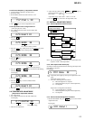
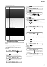
5-8. REWEITING PATCH DATA AFTER REPLACING
THE NONVOLATILE MEMORY
Rewrite the program correction data after replacing the nonvolatile
memory.
5-8-1 Method for rewriting the corrected data
(when using Version 1.000)
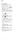
1. Set in Test mode.
2. Set in Manual mode and enter the item number 022.
LCD display
022 PatClr CC
Data.
3. Press the key to reset the patch data.
(Writing is complete if the setting changes to DD.)
LCD display
022 PatClr DD
4. Press the
>
key and enter the item number 023.
LCD display
023 Patch 00
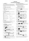
5. Press the
VOL +
key and set the adjustment setting to 01.
LCD display
023 Patch 01
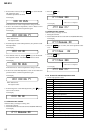
6. Press the key.
LCD display
022 PatClr CC
Data.
This section (address) flashes.
7. Press the
x
key.
(The data section flashes.)
8. Press the
VOL +
and
VOL –
keys and set the adjustment
data while referring to the patch data list.
9. Press the
key and the address section flashes.
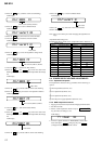
10. Press the
VOL +
keys and set the address value in the next
address for adjustment.
LCD display
023 8922 00
This section (address) flashes.
11. Press the
x
key.
LCD display
023 8922 00
This section (data) flashes.
12. While referring to the patch data table repeat the data correction
write procedure from steps 8 through 11 until the address 899E
is set.
13. Press the
key.
(The address value flashes.)
14. Press the
key to quit the patch data write mode.
LCD display
023 Patch 01
15. Press the key.
LCD display
023 Patch CC
After finished writing data.
LCD display
LCD display
023 Patch DD
16. Turn off the power.