


9
MZ-E300
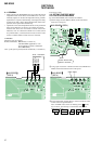
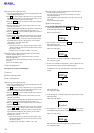
4-6-1. Electrical offset adjustment method
Note: Doing adjustment by the state that a disc does not enter.
1. Confirm the power voltage is 1.5V.
2. Set to the test mode.
3. Press the – key of main unit activates the overall adjustment
mode.
Main unit LCD display
4. Press the + key.
Main unit LCD display
5. Press the + key once more. Adjustment is complete when the
adjustment value appears in the “XX” position.
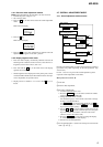
ASS
TEST MODE
(Display Check Mode)
Overall Adjustment
Title Display(ASSY**)
CD overall
Adjustment
.
key
.
VOL – key or key
key
x
MO overall
Adjustment
> N
key
> N
key
key
x
Electrical offset
Adjustment key
VOL + key
key
x
key
x
NV reset
PLAY MODE/DISPLAY key
035:
XX
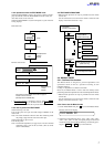
Microprocessor Version 1.10
1 Clear NV.
2 Electric offset adjustment.
3 Rewriting of RAM 633h
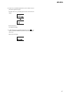
1. switch to manual mode No. 100.
2. Press the DISPLAY key on the remote control unit 6 times
consecutively to enter RAM mode.
3. Change the RAM address to 633h.
Use the following keys on the remote control unit to change
the digits of the RAM address:
“The DISPLAY key for the first digit (hundreds), the x key
for the second digit (tens) and the >B key or the .
key for the third digits (units).”
4. Use the + and – keys on the remote control unit to set the
adjustment value of No.633h to 03h and press once the pause
key on the remote control unit to write this value to NV.
“(If NV is cleared, the value is 00h.)
5. Press the DISPLAY key once more to change the display
to “address and adjustment value display”.
6. Switch to the overall adjustment.
4 CD overall adjustment * (Not to turn off the power between the
items 3 and 4 .)
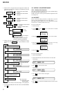
4-6-2. Display segment check mode
1. Enter test mode. Display continuously alternates between the
following three conditions: entire LCD is lit, entire LCD is ex-
tinguished, version info is shown, and so on.
2. Press and hold the x key on the main unit to enter display
segment check mode.
* Should segments not be displayed correctly at this point, a short-
circuited COM terminal and/or SEG terminal on the micropro-
cessor chip (IC801) are possible causes.
3. Display returns to condition “1” as soon as the x key is re-
leased.
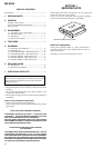
4-7. OVERALL ADJUSTMENT MODE
4-7-1. Overall adjustment mode structure
Perform overall adjustments according to the following procedures
(procedures may differ depending on the microprocessor chip
version used).
For Ver. 1.10, if it is no good in the overall adjustment, please
repeat the overall adjustment several times.