


7
MZ-E300
888:88
130
u
F
1SHUFF
AVLS BASS
All on
All off
Microprocessor
version
display
888
u
008 V1.300
F
1SHUFF PGM
SOUND 1 2 BASS 1 2
All on
All off
Microprocessor
version
display
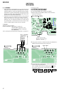
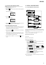
The remote control display varies with the type of
remote control unit used.
(Example shown: RM-MC10L)
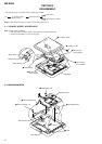
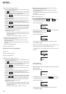
4-2-2. Operations when the TEST MODE is set
When the TEST MODE is entered, the system switches to the dis-
play check mode within the TEST MODE. From this mode, the
other Test modes can be accessed.
When the TEST MODE is set, the LCD repeats a cycle of the fol-
lowing displays:
Main unit LCD
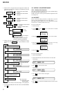
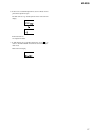
4-4. MANUAL MODE
4-4-1. Outline of the function
The Manual mode is designed to perform adjustments and
operational checks on the set’s operation according to each
individual function.
Usually, no adjustments are made in this mode.
However, the Manual mode is used to clear the memory before
performing automatic adjustments in the Overall Adjustment mode.
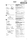
* Manual mode operation can only be performed via the remote
control unit.
Use the connection tool to connect the remote control unit. The
display of the main unit shows “Adj”.
4-4-2. How to set the Manual mode
1. Set the TEST MODE and press + key to set the Manual mode.
Remote control LCD display
000 AAAS CC
Test Mode
(Display Check Mode)
Manual Mode
(Remote control only)
Servo Mode
Audio Mode
Power Mode
OP Alignment Mode
key
key
+
key
+
key
x
x
key
key
.
or
Overall Adjustment Mode
x
Press and hold
down
keyRelease
x
key
Display segment check mode
(Main unit only)
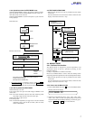
2. When the test mode display shows “100”, “200”, “300”, “500”,
“600”, “700”, “800”, or “900”, the optical pickup can be moved
inside and outside of the SLED perimeter by continuously press-
ing the ( > N or . keys on the main unit.
• The current display is retained as long as either the PLAY
MODE/DISPLAY key on the main unit or the PLAY MODE
key on the remote control unit is pressed and held.
4-2-3. How to release the TEST MODE
When method 1 was used:
Turn off the power and open the solder bridge on BP801 on the
main board.
Note: The solder should be removed clean. The remaining solder
may make a short with the chassis and other part.
When method 2 or 3 was used:
Turn off the power.
Note: If electrical adjustment (see page 8) has not been finished
completely, always start in the test mode. (The set cannot
start in normal mode)
4-3. TEST MODE STRUCTURE
* Manual mode operation can only be performed via the remote
control unit.
Use the connection tool to connect the remote control unit. The
display of the main unit shows “Adj”.
Remote control LCD
Ver 1.2 2001.12