


48
MDX-CA680/CA680X
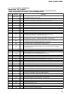
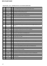
Pin No. Pin Name I/O Description
42 UNISO
O Serial data output to the SONY bus interface (IC505)
43 UNISI
I Serial data input from the SONY bus interface (IC505)
44 UNICKO
O
Serial clock signal output to the MD mechanism controller (IC501) and SONY bus interface
(IC505)
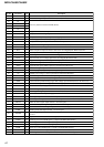
45 IIC SIO I/O
Two-way data IIC bus with the FM/AM tuner unit (TU10), RDS decoder (IC51) (AEP, UK
models only) and electrical volume (IC401)
46 NCO O
Not used (open)
47 IIC CKO O
IIC bus clock signal output to the FM/AM tuner unit (TU10), RDS decoder (IC51) (AEP, UK
models only) and electrical volume (IC401)
48 NCO O
Not used (open)
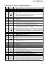
49
TUNON O
Tuner system power supply on/off control signal output to the BA4908 (IC601)
“H”: tuner power on
50 PW ON
O Main system power supply on/off control signal output to the BA4908 (IC601) “H”: power on
51 to 65
NCO O
Not used (open)
66
AMPATT
O
Power amplifier muting on/off control signal output to the power amplifier (IC611)
“L”: muting on
67
AMPON
O
Standby on/off control signal output to the power amplifier (IC611)
“L”: standby mode, “H”: ampifier on
68
NCO O
Not used (open)
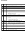
69
ATT
O Audio line muting on/off control signal output “H”: muting on
70
VOLATT
O
Pre amplifier muting on/off control signal output to the electrical volume (IC401)
“L”: muting on
71 to 75
NCO O
Not used (open)
76
COLSW
I
Setting terminal for the illumination color “L”: 2 colors, “H”: 1 color
MDX-CA680: fixed at “L”, MDX-CA680X: fixed at “H”
77
COLSEL
I
Setting terminal for the illumination color “L”: amber, “H”: green
MDX-CA680: not used (fixed at “L”), MDX-CA680X: fixed at “H”
78
DIMSEL
I Setting terminal for the dimmer “L”: no dimmer, “H”: dimmer in (fixed at “L” in this set)
79 to 85
NCO O
Not used (open)
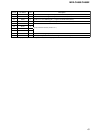
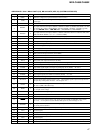
86 EEP SIO I/O Two-way data EEPROM bus with the FM/AM tuner unit (TU10)
87
EEP CKO O
EEPROM bus clock signal output to the FM/AM tuner unit (TU10)
88
NCO O
Not used (open)
89 FLASHW
I
Internal flash memory data write mode detection signal input terminal “L”: data write mode
Not used (fixed at “H”)
90
NS_MASK O
Discharge control signal output for the noise detection circuit “H”: discharge
91 XKEYON O
A/D converter power control signal output
When the KEYACK (pin wh) that controls reference voltage power for key A/D conversion input
is active, “L” is output from this terminal to enable the input
92
DOORIND
O
LED drive signal output of the MD disc slot illumination and Z indicator (LED810, LSW810)
“H”: LED on “H” is output to turn on LED when front panel is opened
93 ILLON O
Power on/off control signal output of the illumination LED and liquid crystal display driver
(IC900) “H”: power on
94
DOORSW I
Front panel open/close detection signal input “L” is input when the front panel is closed
95
DAVSS —
Ground terminal (for D/A converter)
96, 97
RE_IN1, RE_IN0
I Dial pulse input of the rotary encoder (RE901) (for VOLUME control)
98
RCIN1
I Rotary remote commander shift key input terminal “L”: shift key on
99 NIL I Not used (fixed at “L”)
100
DAVCC —
Power supply terminal (+5V) (for D/A converter)