


57
MDS-S50
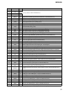
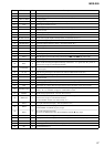
Pin No. Pin Name I/O Description
76 VSS
— Ground terminal
77 to 85 A17 to A9 O
Address signal output to the flash memory Not used (open)
86 to 89 SEL1 to SEL4
I Not used (open)
90 WP O
Writing protect signal output to the flash memory “L” active Not used (fixed at “L”)
91 VCC
— Power supply terminal (+3.3V)
92 A8 O
Address signal output to the flash memory Not used (open)
93 VSS
— Ground terminal
94 to 101 A7 to A0 O
Address signal output to the flash memory Not used (open)
102 to 113 D15 to D4 I/O
Two-way data bus with the flash memory Not used (open)
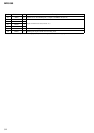
114
KEYBD-CLKCTL
O Clock control signal output to the key board Not used (fixed at “L”)
115
I2CBUSY
I
Busy monitor signal input from the IIC bus
116 KEYBD-DAT
I Serial data input from the key board Not used (fixed at “H”)
117 REC VOL A O
Not used (open)
118 REC VOL B O
Not used (open)
119 to 12
2
D3 to D0 I/O
Two-way data bus with the flash memory Not used (open)
123 JOG0 I
JOG dial pulse input from the rotary encoder (S713 . AMS >) (A phase input)
124 JOG1 I
JOG dial pulse input from the rotary encoder (S713 . AMS >) (B phase input)
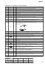
125
LATCH
O
Not used (open)
126
REC
O
Power on/off control signal output for the beep sound drive “L”: power off, “H”: power on
(Used for the except US and Canadian models)
127
COAX/OPT
O
Optical in or coaxial in selection signal output terminal “L”: optical in, “H”: coaxial in
Not used (open)
128
FL-CS
O
Chip select signal output to the fluorescent indicator tube/LED driver (IC761)
129
I2CPOWER
I
Power supply detection signal input from the IIC bus
130 VSS
— Ground terminal
131
STB
O
Relay drive signal output for the power on/off “L”: standby, “H”: power on
132 VCC
— Power supply terminal (+3.3V)
133 IOP
I Optical pick-up voltage detection signal input from the automatic power control circuit
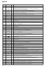
134
DESTINATION
I
Destination setting input terminal “L”: AEP, UK, Hong Kong, Argentine, and Australian
models, “H”: US, Canadian, Singapore, and Brazilian models
135
MODEL
I
Model setting input terminal Fixed at “M” in this set
136
BEEP SW
I
BEEP switch (S831) input terminal “L”: beep off, “H”: beep on
(Used for the except US and Canadian models)
US and Canadian models: Not used (fixed at “L”)
137
KEY3
I
Key input terminal (A/D input) Not used (fixed at “H”)
138
KEY2
I
Key input terminal (A/D input) S721 to S724 and S726 (INPUT, PLAY MODE, REC MODE,
LEVEL/DISPLAY/CHAR, I/1) keys input
139
KEY1
I
Key input terminal (A/D input)
S711 to S715 (MENU/NO, YES, PUSH ENTER, CLEAR, Z) keys input
140 AVSS
— Ground terminal (for analog system )
141
KEY0
I
Key input terminal (A/D input) S701 to S705 (z, x, M, m, u) keys input
142 VREF I Reference voltage (+3.3V) input terminal (for A/D converter)
143 AVCC
— Power supply terminal (+3.3V) (for analog system )
144
NC
O
Not used (fixed at “L”)