masterpage:Left
(3 column)
filename[F:\My Document\mds-
s50\4230403131\4230403131\423040313MDSS50U2\GB05OPE-U2.fm]
model name1[MDS-S50]]
[4-230-403-13(1)]
26
Naming a track or MD (continued)
Erasing a track or disc name
Use this function to erase the name of a track or
disc.
1 While the deck is stopped, playing,
recording, or paused, press MENU/NO.
“Edit Menu” appears in the display.
2 Turn AMS (or press ./>
repeatedly) until “Name ?” appears,
then press AMS or YES.
3 Turn AMS (or press ./>
repeatedly) until “Nm Erase ?” appears,
then press AMS or YES.
4 Turn AMS (or press ./>
repeatedly) until the number of the track
(when erasing the track name) or “Disc”
(when erasing the disc name) flashes,
then press AMS or YES.
“Complete!!” appears.
To erase all the names on the MD
Select “Nm All Ers?”,thenpressAMSorYES
twice in step 3 above.
You can change the volume of recorded tracks
using S.F (Scale Factor) Edit. The original track
is recorded over at the new recording level.
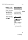
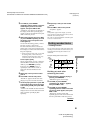
When changing the recording level, you can
select Fade-in Recording to gradually increase
the signal level at the start of recording, or
Fade-out Recording to gradually decrease the
signal level at the end of recording.
Changing the overall
recording level
1 Press MENU/NO.
“Edit Menu” appears in the display.
2 Turn AMS (or press ./>
repeatedly) until “S.F Edit?” appears,
then press AMS or YES.
3 Turn AMS (or press ./>
repeatedly) until “Tr Level ?” appears,
then press AMS or YES.
4 Turn AMS (or press ./>
repeatedly) until the track number you
want to change the recording level
appears, then press AMS or YES.
“Level 0dB” appears in the display.
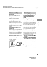
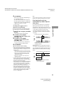
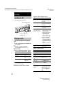
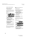
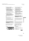
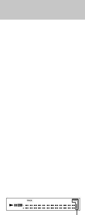
5 While monitoring the sound, turn AMS
(or press ./> repeatedly) to
change the recorded level without
turning on “OVER” on the peak level
meters.
Avoid turning on these indicators
Changing the recorded
level after recording
— S.F EDIT