Editing Recorded MDs
masterpage:Left
(3 column)
filename[F:\My Document\mds-
s50\4230403131\4230403131\423040313MDSS50U2\GB05OPE-U2.fm]
model name1[MDS-S50]]
[4-230-403-13(1)]
25
3 Enter a character using letter/number
buttons.
If you have selected uppercase or
lowercase letters
1 Press the corresponding letter/number
button repeatedly until the character to
be entered flashes.
Or,pressthebuttononceandpress
./> repeatedly.
To select symbols, press .
repeatedly while “A” is flashing.
2 Press M.
The flashing character is entered and
lights continuously and the cursor shifts
to the right.
If you have selected numbers
Press the corresponding number button.
The number is entered and the cursor shifts
to the right.
4 Repeat steps 2 and 3 to enter the rest of
the name.
To change a character
Pressm/M repeatedlyuntil the character
to be changed flashes, press CLEARto erase
the character, then repeat steps 2 and 3.
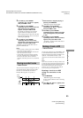
5 Press YES.
The whole name appears in the display,
followed by “Complete!!”.
Copying a track or disc name
You can copy an existing track or disc name and
useittonameanothertrackonthesamediscor
thediscitself.
1 While the deck is stopped, playing, or
paused, press MENU/NO.
“Edit Menu” appears in the display.
2 Turn AMS (or press ./>
repeatedly) until “Name ?” appears,
then press AMS or YES.
3 Turn AMS (or press ./>
repeatedly) until “Nm Copy ?” appears,
then press AMS or YES.
4 Turn AMS (or press ./>
repeatedly) until the track number
(when copying the track name) or
“Disc” (when copying the disc name)
flashes, then press AMS or YES to copy
the selected name.
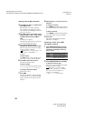
When “No Name” appears in the display
The selected track or disc has no name.
5 Turn AMS (or press ./>
repeatedly) until the track number
(when naming a track) or “Disc” (when
naming a disc) flashes, then press AMS
or YES to enter the copied name.
“Complete!!” appears.
Tip
When “Overwrite ??” appears in step 5 above, the
track or the disc selected in step 5 already has a name.
If you wish to replace the name, press AMS or YES
againwhiletheindicationappearsinthedisplay.
If the track has been recorded in MD LP mode with
the “LPstamp On” setting (page 10), “Overwrite ??”
also appears even if a track name is not assigned. In
this case if you copy the track name, the “LP:”
indication disappears from the track name.
Renaming a track or MD
1 Press NAME EDIT/SELECT on the
remote while the deck is in one of the
operating modes listed below,
depending on what you want to rename:
A track or disc name appears in the display.
2 Press CLEAR until the selected name is
erased completely.
3 Dosteps5to8of“Naming a track or an
MD using the controls on the deck” on
page 24 or steps 2 to 4 of “Naming a
track or an MD using the remote” on
page 24.
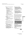
4 Press YES.
The whole name appears in the display,
followed by “Complete!!”.
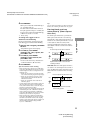
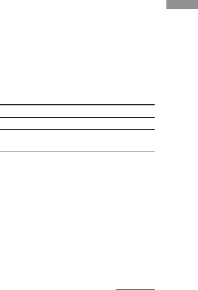
To rename Press while
A track The track number is displayed
The MD The deck is stopped with total
number of tracks displayed
continued