Other Functions
masterpage:Left
(3 column)
filename[F:\My Document\mds-
s50\4230403131\4230403131\423040313MDSS50U2\GB05OPE-U2.fm]
model name1[MDS-S50]]
[4-230-403-13(1)]
29
Tip
Do the following procedure to specify the fade-in or
fade-out duration for playback or recording.
1 While the deck is stopped, press MENU/NO
twice.
“Setup Menu” appears in the display.
2 Turn AMS (or press ./> repeatedly)
to select the setting, then press AMS or
YES.
3 Turn AMS (or press ./> repeatedly)
to select the duration, then press AMS or
YES.
Both the Fade-in and Fade-out durations can be
set in 0.1 second steps.
4 Press MENU/NO.
You can set the deck so that it turns off
automatically after 60 minutes.
1 While the deck is stopped, press MENU/
NO twice.
“Setup Menu” appears in the display.
2 Turn AMS (or press ./>
repeatedly) until “Sleep Off” appears in
the display, then press AMS or YES.
3 Turn AMS (or press ./>
repeatedly) to select the setting, then
press AMS or YES.
4 Press MENU/NO.
Tip
You can check the remaining time.
Once you turn on Sleep Timer, the remaining time is
displayed when you select “Sleep” in Setup Menu.
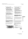
To change the
duration of
Select
Fade-in Play/Recording F.in
Fade-out Play/Recording F.out
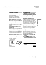
Falling asleep to music
— Sleep Timer
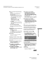
To Select
Turn on Sleep Timer Sleep On
Turn off Sleep Timer Sleep Off (factory
setting)