27
GB
Getting Started
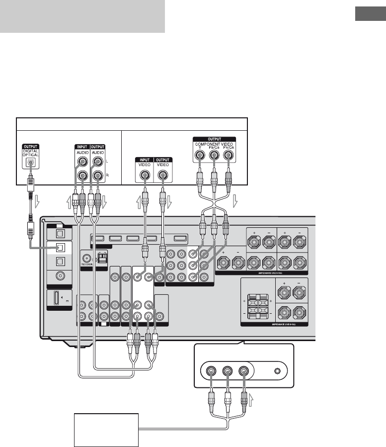
The following illustration shows how to
connect a component which has analog jacks
such as a VCR, DVD recorder, etc.
It is not necessary to connect all the cords.
Connect audio and video cords according to
the jacks of your components.
Notes
• Be sure to change the factory setting of the VIDEO
1 input button on the remote so that you can use the
button to control your DVD recorder. For details,
see “Programming the remote” (page 83).
•You can also rename the VIDEO 1 input so that it
can be displayed on the receiver’s display. For
details, see “Naming inputs” (page 80).
•When connecting optical digital cords, insert the
plugs straight in until they click into place.
•Do not bend or tie optical digital cords.
Connecting components with
analog video and audio jack
VIDEO 2 IN/PORTABLE AV IN
AUTO CAL MIC
L
R
DIGITAL
DMPORT
(ASSIGNABLE)
OPTICAL
OPTICAL
IN
COAXIAL
DVD
IN
TV
SAT
IN
DC5V
0.7A MAX
AM
FM
ANTENNA
SAT IN DVD IN BD IN
VIDEO 1 IN OUT
HDMI
AUDIO
OUT
SPEAKERS
SPEAKERS
CENTER
SURROUND BACK
FRONT AFRONT B
L
R
SURROUND
L
R
L
L
R
R
COMPONENT VIDEO
SAT IN DVD IN
Y
P
B
/
C
B
P
R
/
C
R
AUDIO
IN
VIDEO
IN
SAT
AUDIO
IN
VIDEO
IN
MONITOR
IN
TV
OUT
AUDIO
OUT
VIDEO
OUT
AUDIO
IN
VIDEO
IN
VIDEO 1 IN
SA-CD/CD/CD-R
VIDEO L AUDIO R
VIDEO 1
IN
IN
VIDEO 1
VIDEO
OUT
MONITOR OUT
SUBWOOFER
DVD
VCR, DVD recorder
B
Camcorder/
video game
E
Audio signals
Video signals
C
AOptical digital cord (not supplied)
BAudio cord (not supplied)
CVideo cord (not supplied)
DComponent video cord (not supplied)
EAudio/video cord (not supplied)
AD
(On the front panel)


