


99-00855-20 C0 Installing Your SMART Audio 240 System 7
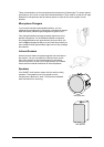
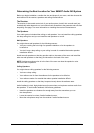
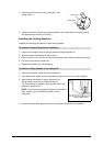
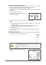
1. If you’ve connected an external sensor to EXT SENSOR
INPUT 1, set the SENSOR SELECT switch on the side of the
receiver to EXT. This disables the infrared sensor on the front
of the receiver.
OR
If you haven’t connected an external sensor to EXT SENSOR
INPUT 1, set the SENSOR SELECT switch on the side of the
receiver to INT. This disables the EXT SENSOR INPUT 1 connection on the back of
the receiver.
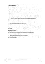
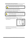
Installing the Ceiling Infrared Sensor
1. Remove the ceiling tile that you want to attach the sensor to.
2. Remove the two screws that attach the sensor’s mounting bracket to the ceiling sensor,
and then detach the bracket.
3. Place the bracket on the ceiling tile you removed, and then mark two screw holes and the
center hole with a pencil.
4. Remove the bracket from the tile, and then drill the two screw holes and the 1" (2.5 cm)
center hole using a power drill.
5. Position the sensor on the underside of the tile so that the screw holes align with the scew
holes in the tile, and that the F-type cable connector aligns with the center hole.
6. Position the mounting bracket on the other side of the tile, and then tighten the two bracket
screws through the bracket, tile and bracket screw holes in the sensor.
7. Connect the RG-59 cable to the F-type jack on the ceiling sensor.
8. Replace the ceiling tile in the ceiling grid.
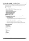
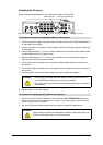
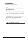
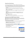
1. Use a pair of pliers to bend up the mounting bracket 90° at
the points shown in the diagram.
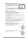
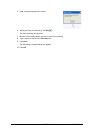
2. Use a pair of pliers to bend flat the ends of the mounting
bracket 90° at the points shown in diagram.
To select the ceiling or the receiver infrared sensor
To attach the ceiling infrared sensor to a drop-ceiling tile
To attach the ceiling infrared sensor to a solid ceiling
Sensor Select Switch
Bend Here
Bend Here